background image

28

AV Select and Setup

It is possible to connect a variety of additional equipment to this TV. The following pages detail how to

connect external equipment to both the front and rear of the TV.

Once your equipment is connected, use the following procedure to view the input:
Press the

TV/AV

menu button

Press the relevant on screen selector key to select the AV source you wish to view

(for example, press the green button to select

AV2

if you have connected a video

recorder to the AV2 SCART socket).

The on screen selector keys that appear clear after a few seconds. If you want to select

an input when the keys are not shown, press the

TV/AV

key once more and the keys

will reappear.

Notes:

D

This television may automatically switch over to the AV mode if the connected device sends a

switch signal to the SCART cable connector. In this case, the “EC” will be displayed in the left top

corner of the screen and the signal from the AV equipment (for the RGB signal the “EC/RGB” will be

displayed).The picture received will remain the same when the TV programme is changed.

D

You may switch back to the television by pressing button

“TV/AV”

or by disconnecting the AV

device.

D

You can also select an AV source using the

TV/AV

button on the control panel on the front of your

TV. Press the

TV/AV

button repeatedly until you reach the AV source you wish to view.

D

When in

AV mode

a reduced number of options are available in the

SOUND

and

SETUP

menus

(eg: in the Setup menu there is no

Tuning menu

option).

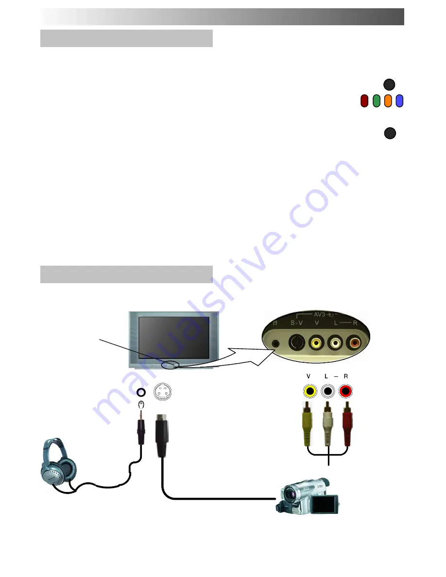
Front sockets

Additional equipment can be connected at the front of the TV via a 4 pin S---Video socket (AV3), RCA

Audio / Video sockets (AV3) and a headphone socket.

S---V

Press and

release to open

CAMCORDER

Output from

Headphones

socket

3.5mm Stereo

Plug

STEREO HEADPHONES

with 3.5mm Plug

Video input to

S---Video

socket

Video input

to

V

socket

Audio input

to

L / R

sockets

RCA Video

cable

2 x RCA

Audio

cables

Notes:

D

Additional equipment and cables shown are not supplied with this TV set.

D

For S---Video socket wiring information see page 29.

AUDIO / VIDEO CONNECTIONS

TV/AV

TV/AV

Summary of Contents for TX-28PX10DM

Page 1: ...naso nic Panasonic Panasonic Panasonic Panasonic Panasoni c Panasonic Panasonic Panasonic Panasonic Panasonic Panasonic Panasonic Panasonic Panasonic Panasonic Pa nasonic Panasonic Panasonic Panasonic...

Page 2: ...cautions 3 Accessories 4 Quick Start Guide 5 Basic Controls 8 Using the On Screen Displays 9 Aspect controls 10 Still Control 12 Picture and Text 12 Picture Menu 13 Sound Menu 14 Setup Menu 15 Tuning...

Page 3: ...ce static electricity care must be taken whenever touching the TV screen D Adequate ventilation is essential to prevent failure of electrical components we recommend that a gap of at least 5cm is left...

Page 4: ...sure that the batteries are fitted the correct way round D Do not mix old batteries with new batteries Remove old exhausted batteries immediately D Do not mix different battery types i e Alkaline and...

Page 5: ...5 1 OR VCR DVD R AV2 AV1 AV2 AV1 Plug in aerial and connect ancillary equipment SATELLITE RECEIVER First ensure that the VCR is in Standby mode Plug in TV and switch on 2 QUICK START GUIDE...

Page 6: ...g a new Q Link compatible VCR you can now switch it ON Downloaded tuning data will match the television s If you are installing a new NEXTVIEWLINK compatible VCR you will need to initiate download man...

Page 7: ...ears to be level Press the F button again to return to normal viewing Close the flap to prevent damage Adjust Volume Change Programme You are now ready to begin viewing programmes The cursor controls...

Page 8: ...function set tings F Function select Displays the On Screen Display functions use repeatedly to select from the available functions Volume Contrast Brightness Colour Sharpness Tint in NTSC mode Bass T...

Page 9: ...indicates which keys on the remote control are used to navigate the menu shown see above for descriptions of button functions Note D If the HELP button is pressed while a menu is displayed the Instru...

Page 10: ...left of the screen if a widescreeen identification signal WSS is found or a signal is found through a Scart socket Panasonic Auto switches into 16 9 widescreen ratio Panasonic Auto appears in the top...

Page 11: ...ides of thepicture The 4 3 picture will be stretched horizontally so that the image fills the screen this is done in such a way that the stretching is only obvious at the left and right edges of the s...

Page 12: ...you to freeze the picture at any time Press the TELETEXT button to move between watching the current programme viewing teletext and the picture and text feature Picture andtext lets you see the curre...

Page 13: ...and the viewing conditions The Tint adjustment will only appear as a menu item if you have an NTSC signal source connected to the TV and will allow adjustment of the hue The Colour balance setting al...

Page 14: ...d between the left and right speakers Adjustment can be made so that the level from the speakers will suit your listening position Can be adjusted independantly of the TV speakers so that everyone can...

Page 15: ...u to enable or disable data communication with a compatible VCR See page 23 Select character set so that all characters needed are availabe for text on teletext pages eg cyrillic characters etc Mode L...

Page 16: ...l tuning menu allows individual programme positions to be tuned manually See page 22 Stations can be finely tuned using the Fine tuning adjustment The Colour system menu allows you to decide the corre...

Page 17: ...anges If you have finished in the Programme edit menu press the TV AV button to exit To delete an unwanted programme position Make sure the cursor is in the Prog column Press the Red button on remote...

Page 18: ...To tune a programme position Move to the Chan column Increase or decrease channel number or use the C key for Direct Channel Access or use the C and buttons for Direct Channel Access in hyperband see...

Page 19: ...ot available for To change the TV system for a programme position Move to the Sys column Choose the required sound system SC1 PAL B G SECAM B G SC2 PAL I SC3 PAL D K SECAM D K F SECAM L L Press STR to...

Page 20: ...VCR This might take a few seconds depending on the number of stations stored If the message Q Link Unable to download check your VCR appears on the screen the television is unable to send the programm...

Page 21: ...ompatible VCR is connected via the AV2 socket programme data will be sent to the VCR via Q Link see page 23 Once this operation is completed the TV will display programme position 1 TUNING MENU AUTO S...

Page 22: ...n to exit Manual tuning Front panel Press the F button Front panel until Tuning mode is reached Press the or button to access Tuning mode Press the TV AV button to move between Change programme Search...

Page 23: ...he DIRECT TV REC button A message sent from the VCR will appear on screen showing what is being recorded or if it is not possible to record VCR recording preset prog VCR recording TV source No recordi...

Page 24: ...p menu and set the Q Link option to Off See page 15 Important Note Not all VCRs support this type of data communication system Some may support certain features but not others See the VCR handbook for...

Page 25: ...y mode press to view the picture rapidly forward DVD R Press once to skip to the next track In play mode press and hold to view the picture rapidly forward Skip Fast Forward Cue VCR Press to rewind th...

Page 26: ...D The Green button will select the next available page UP D The Red button will select the next available page DOWN What are the advantages D Page selection at the touch of a single button D Easy to u...

Page 27: ...e automatic changing of the sub pages to reach the sub page you require As each sub page is found its number is displayed at the top of the page so that you may select it as more sub pages are picked...

Page 28: ...equipment for the RGB signal the EC RGB willbe displayed The picture received will remain the same when the TV programme is changed D You may switch back to the television by pressing button TV AV or...

Page 29: ...table inputs for AV1 AV4 include RGB Red Green Blue S C In on Pin 15 S C In only applies to AV4 AV4 Pins 15 and 20 are dependent on AV4 S VHS VIDEO switching AV2 Scart socket S Video Q Link Socket Ear...

Page 30: ...VIDEO CAMCORDER VCR SET TOP BOX DVD PLAYER CAMCORDER GAMES CONSOLE COMPUTER RGB Input Output from AV1 Scart Socket Scart cable Input Output from AV2 Scart Socket Q Link data Input Output from AV4 Sca...

Page 31: ...plugged into A C outlet Not switched on Picture Sound controls set at minimum levels Check if in standby mode No Colour Normal Sound Colour controls set at minimum levels Poor or Distorted Picture Wea...

Page 32: ...69 CATV S01 S05 CATV S1 S10 M1 M10 CATV S11 S20 U1 U10 CATV S21 S41 Hyperband PAL D K SECAM D K VHF R1 R2 VHF R3 R5 Systems Band name VHF R1 R2 VHF R3 R5 VHF R6 R12 UHF E21 E69 PAL 525 60 Playback of...

Reviews: