


FAQs, etc.
•
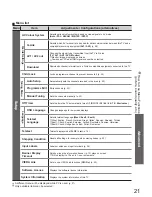
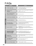
Technical Information
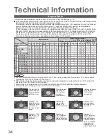
Signal name
Aspect modes
Aspect Control Signal
Widescreen signal (WSS) Control signal through SCART
(pin 8) or HDMI terminal
Auto 16:9 14:9 Just 4:3 4:3
Full Zoom1 Zoom2 Zoom3 TV AV1 AV2 AV3 Component AV1 AV2
HDMI
1
HDMI
2
TV/A
V1/A
V2/A
V3
PAL
O O O O O
-
O
O
O
O O O O
-
O
O
-
-
PAL 525/60
O O O O O
-
O
O
O
-
-
-
-
-
O
O
-
-
M.NTSC
O O O O O
-
O
O
O
-
-
-
-
-
O
O
-
-
NTSC(AV input only) O O O O O
-
O
O
O
-
-
-
-
-
O
O
-
-
Component/HDMI
SD
525(480)/60i
O O O O O
-
O
O
O
-
-
-
-
-
-
-
O
O
525(480)/60p
O O O O O
-
O
O
O
-
-
-
-
-
-
-
O
O
625(576)/50i
O O O O O
-
O
O
O
-
-
-
-
O
-
-
O
O
625(576)/50p
O O O O O
-
O
O
O
-
-
-
-
O
-
-
O
O
HD
750(720)/50p
O O O O O O
O
O
O
-
-
-
-
-
-
-
O
O
750(720)/60p
O O O O O O
O
O
O
-
-
-
-
-
-
-
O
O
1125(1080)/50i O O O O O O
O
O
O
-
-
-
-
-
-
-
O
O
1125(1080)/60i O O O O O O
O
O
O
-
-
-
-
-
-
-
O
O
1125(1080)/50p O O O O O O
O
O
O
-
-
-
-
-
-
-
O
O
1125(1080)/60p O O O O O O
O
O
O
-
-
-
-
-
-
-
O
O
PC input
-
O
- -
O
-
-
-
-
-
-
-
-
-
-
-
-
-
34
35
Technical Information
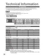
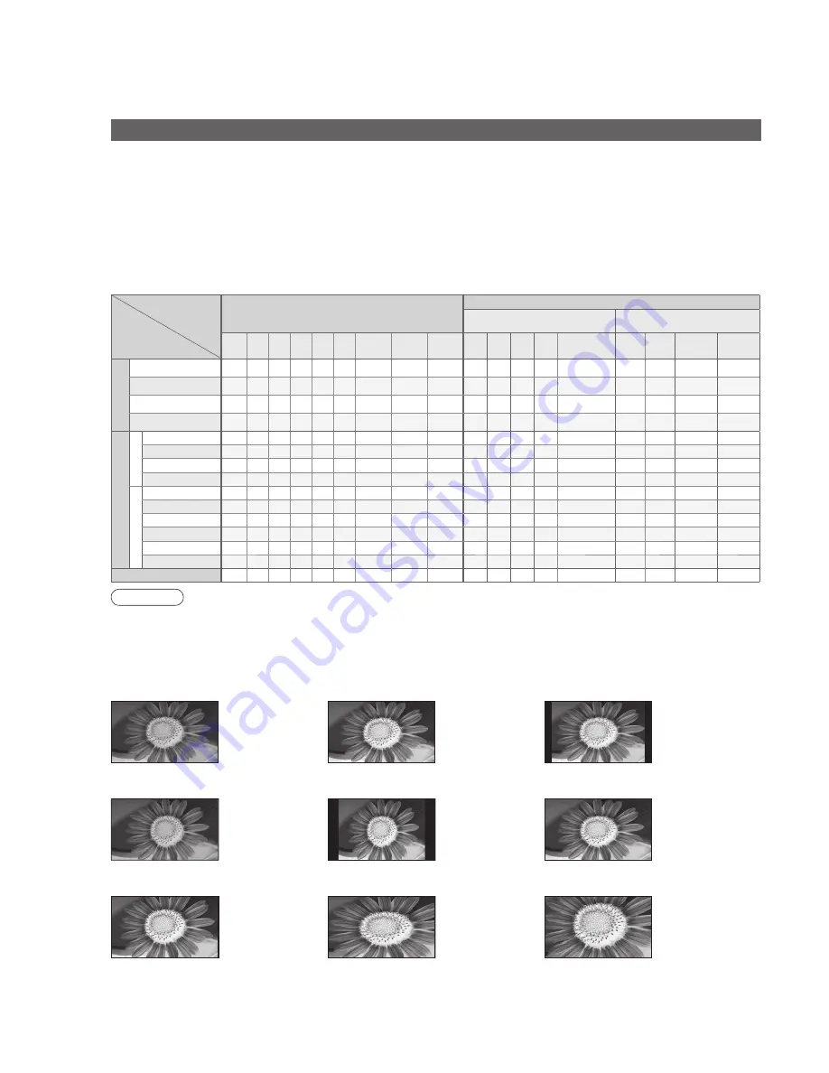
Aspect Ratio
Note
•
The ratio varies depending on the programme, etc. If the ratio is greater than the standard “16:9”, black bands
may appear at the top and bottom of the screen.
•
If the screen size looks unusual when a widescreen-recorded programme is played back on a VCR, adjust the
tracking of the VCR. (See the VCR manual.)
•
Aspect mode can be memorized for SD (Standard de
fi
nition) and HD (High de
fi
nition) signals separately.
•
To select the ratio manually: (Only “16:9” or “4:3” in PC mode)
The optimum size and aspect can be chosen, and you can enjoy
fi
ner images. (p. 13)
■
Auto: Auto aspect determines the best aspect ratio to use to
fi
ll your screen. It does this using a four step process
to determine if the picture being viewed is a widescreen picture.
Just
14:9
16:9
Zoom3
Zoom2
Zoom1
Directly displays
the image at
“16:9” without
distortion
(anamorphic).
Displays a “16:9”
letterbox or “4:3”
image without
distortion.
Displays the image
at the standard
“14:9” without
enlargement.
Displays a
“16:9” letterbox
(anamorphic)
image full-screen
without distortion.
Displays a 4:3
image full-screen.
Stretching is only
noticeable at
the left and right
edges.
Displays a
“2.35:1” letterbox
(anamorphic)
image full-screen
without distortion.
At “16:9”, displays
the image at its
maximum (with
slight enlargement).
Auto
The best ratio is
chosen and the
picture expanded
to
fi
ll the screen.
If Auto aspect detects a widescreen signal it switches into the appropriate 16:9 or 14:9 widescreen mode. If Auto aspect
does not detect a widescreen signal then this advanced TV enhances the picture for optimum viewing pleasure.
The text shown on the screen indicates how Auto aspect determined which ratio to use:
“WIDE” appears in the top left of the screen if a widescreen identi
fi
cation signal (WSS) is found or a signal found
through a SCART terminal. Auto aspect switches to the appropriate 16:9 or 14:9 widescreen ratio. This function
will also work in any aspect mode. “Auto” appears in the top left of the screen if black stripes above and below
the picture are detected. Auto aspect chooses the best ratio and expands the picture to
fi
ll the screen. This
process can take several minutes, depending on the darkness of the picture.
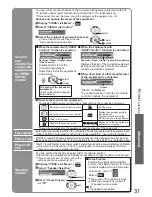
•
This function may not work normally depending on the equipment condition.
•
Image or sound may not be available for the
fi
rst few seconds when the playback starts.
•
Image or sound may not be available for the
fi
rst few seconds when Input mode is switched.
•
Volume function will be displayed when adjusting the volume of the equipment.
•
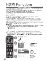
Easy playback is also available by using the remote control for Ampli
fi
er or Player theatre. Read the manuals of
the equipment.
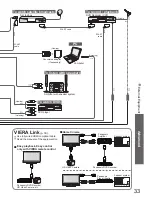
•
If you connect the same kind of equipment at once (for example: one DIGA to HDMI1 / another DIGA to HDMI2),
VIERA Link is available for the terminal with the smaller number.
•
“HDAVI Control 2” is the newest standard (current as of February, 2007) for Panasonic’s HDAVI Control
compatible equipment. This standard is compatible with Panasonic’s conventional HDAVI equipment.
HDMI connections to some Panasonic equipment allow you to interface them automatically. (p. 30)
VIERA Link “
Control
TM
”
4:3 Full
Displays a “4:3”
image enlarged
horizontally to
fi
t
the screen.
4:3
Displays the
image at the
standard “4:3”
without distortion.
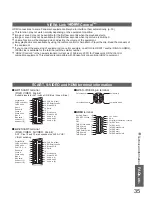
SCART, S-VIDEO and HDMI terminal information
Socket Earth
CVBS out (video)
CVBS earth
Red in
Red earth
Green in
Green earth
Blue in
Blue earth
Audio out (L)
Audio out (R)
CVBS in (video)
RGB status earth
Status RGB
Earth
--
Q-Link data
Status CVBS
Audio in (L)
Audio earth
Audio in (R)
21
19
17
15
13
11
9
7
5
3
1
20
18
16
14
12
10
8
6
4
2
■
AV1
SCART terminal
(RGB, VIDEO, Q-Link)
Suitable inputs for AV1 include RGB (Red / Green / Blue).
Chrominance in
Socket Earth
CVBS out (video)
CVBS earth
Red in, S.C. - in
Red earth
Green in
Green earth
Blue in
Blue earth
Audio out (L)
Audio out (R)
CVBS in (video)
RGB status earth
Status RGB
Earth
--
Q-Link data
Status CVBS
Audio in (L)
Audio earth
Audio in (R)
21
19
17
15
13
11
9
7
5
3
1
20
18
16
14
12
10
8
6
4
2
Luminance in
Chrominance earth
Luminance earth
■
AV3
S-VIDEO 4 pin terminal
■
AV2
SCART terminal
(RGB, VIDEO, S-VIDEO, Q-Link)
AV2 - Pins 15 and 20 are dependent on AV2 S-VHS /
VIDEO switching.
Hot Plug Detect
DDC/CEC Ground
SCL
CEC
TMDS Clock Shield
TMDS Data0
−
TMDS Data0+
TMDS Data1 Shield
TMDS Data2
−
TMDS Data2+
+5V Power
SDA
Reserved (in cable but N.C. on device)
TMDS Clock
−
TMDS Clock+
TMDS Data0 Shield
TMDS Data1
−
TMDS Data1+
TMDS Data2 Shield
19
17
15
13
11
9
7
5
3
1
18
16
14
12
10
8
6
4
2
■
HDMI
terminal