background image

REMOVING COMPUTER from the DOCK

1. Push latch button in (Unlock with key if locked).
2. Lift the back of the computer off of the locating pins.
3. Lift the computer out from under the front retainer tab.

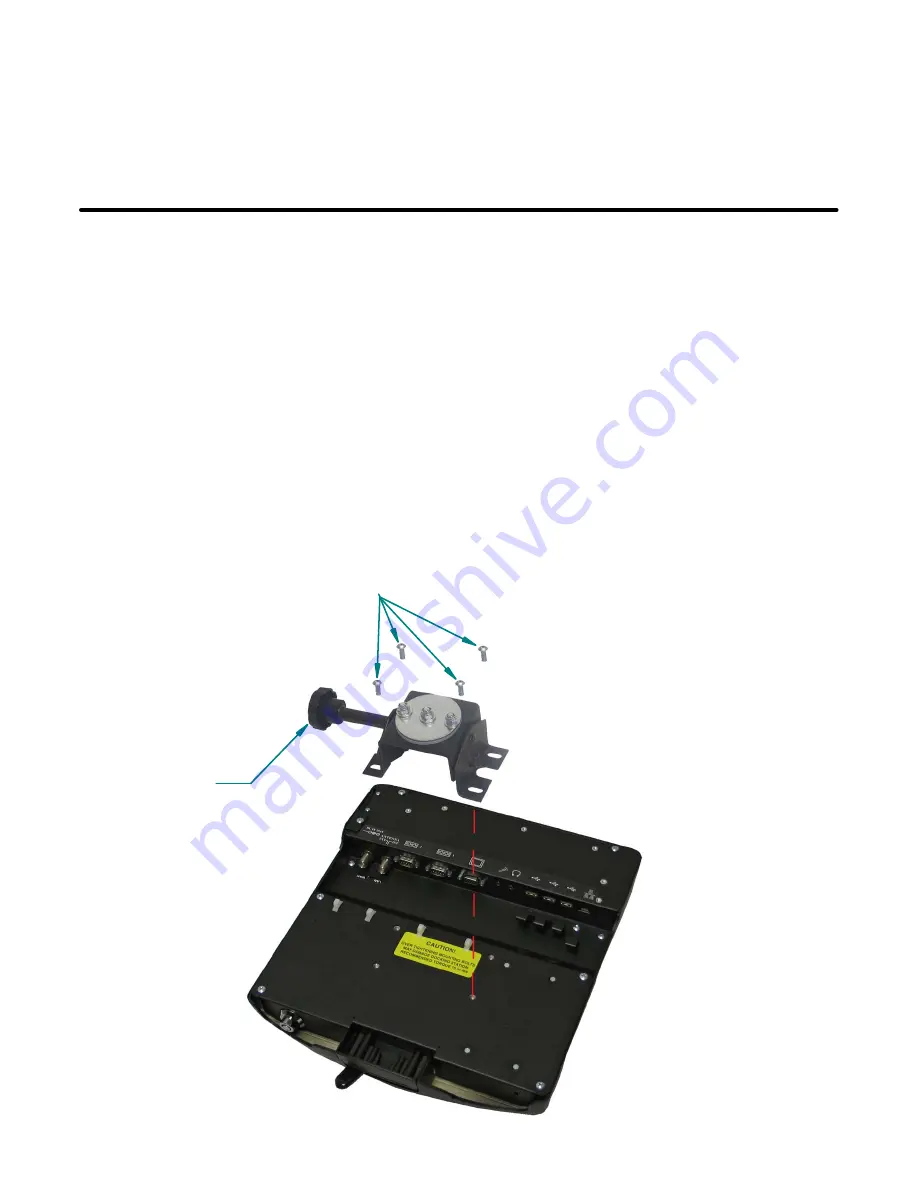
MOUNTING THE DOCKING STATION

Mount docking station to mounting system using the four 1/4-20unc mounting holes on the
bottom of the dock.  Four 1/4-20unc X .50 Button Head Mounting Screws are provided in the
hardware bag.

** Recommended Torque 75 in-lbs.  Over Tightening
    Mounting Hardware May Damage Docking Station

.

This docking station is designed to be used with a variety of Gamber-Johnson mounting
systems. Installation instructions for other Gamber-Johnson products are provided with each
individual product.

(4) 1/4-20 X .50 Button 
Head Mounting Screws

Clevis 

Not Included

Pg 7

Summary of Contents for The Toughbook 31

Page 1: ...Program copyright 2010 Gamber Johnson LLC Printing Spec PS 001 This instruction sheet is for the following products Panasonic Toughbook CF 31 docking station with No integrated high gain antenna pass thru cables Item No 7160 0263 00 Button lock No RF Item No 7160 0263 04 Button lock No RF Int power Item No 7160 0263 07 Auto lock No RF Item No 7160 0263 10 Auto lock No RF Int power Panasonic Toughb...

Page 2: ...Panasonic Toughbook 31 MAG Docking Station Pg 2 ...

Page 3: ... itself 2 Insert computer into docking station and verify that the computer is operating in the dock 3 Interconnect entire assembly and verify start up of all components including other equipment printers modems scanners etc Gamber Johnson recommends positioning of all mounts and equipment in the vehicle prior to the actual install to verify that mounting locations are safe and practical CAUTION I...

Page 4: ...l Strap located in the hardware bag to the power jack as shown Figure 2 Plug the power jack into the input jack located on the port replicator circuit board inside the docking station and tuck the pull strap into the docking station as shown Figure 3 Replace the Power Cable Cover to hold the power jack in place as shown in Figure 4 Figure 1 Figure 2 Figure 3 Figure 4 Remove 8 32unc screw and Power...

Page 5: ...y the customer are odd sized and do not fit with the secondary restraint bracket simply remove the bracket and restrain the cables with the additional tie wrap anchors supplied in the hardware bag Figure 6 WIRELESS ANTENNA SWITCH If using an external antenna connected by cable to the LAN WAN ports on the dock Position the switch toward the EXT side See Figure 5 If using the wireless antenna built ...

Page 6: ...mputer pressing down onto the Alignment Pins 4 Pull the docking handle towards the left side of the dock until the latch catches and holds the handle See Figure 9 The push button latch can be locked for added security 5 Unit is powered and ready for use Docking station will operate with computer screen opened or closed Figure 7 Figure 8 Figure 9 Sliding Door Docking Connector Alignment Pins Align ...

Page 7: ... 4 20unc mounting holes on the bottom of the dock Four 1 4 20unc X 50 Button Head Mounting Screws are provided in the hardware bag Recommended Torque 75 in lbs Over Tightening Mounting Hardware May Damage Docking Station This docking station is designed to be used with a variety of Gamber Johnson mounting systems Installation instructions for other Gamber Johnson products are provided with each in...

Page 8: ...With computer installed in the dock the Dock Indicating LED located on the right side of the dock can be used as a troubleshooting tool See Figure 11 GREEN All ports are ready to use ORANGE USB port and LAN port do not function external power is not connected RED PC is not supported or connection is not made RED BLINKING Error has occured in the firmware Stop using at once and contact Panasonic Te...

Reviews: