20
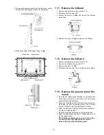
7.14. Remove the G-Board and GS-
Board
1. Remove the Front bracket. (See section 7.13.)
2. Remove the screws (
×
2 ).
3. Remove the screws (
×
3 ).
4. Remove the Front shield case front.
5. Disconnect the connector (GS52).
6. Remove the screws (
×
2 ).
7. Remove the Front shield top.
8. Remove the screws (
×
2
) and remove the GS-Board.
9. Remove the screws (
×
3 ).
10. Disconnect the connector (G51) and remove the G-
Board.
7.15. Remove the Speakers
1. Disconnect the relay connectors
2. Remove the screws (
×
4
each) and remove the
Speaker (L, R).
7.16. Remove the Plasma panel sec-
tion from the Cabinet assy
(glass)
1. Remove the stand brackets (left, right) fastening screw
(
×
1
each).
2. Remove the cabinet assy and the plasma panel fastening
screws (
×
7 ).
Summary of Contents for TH-C42HD18
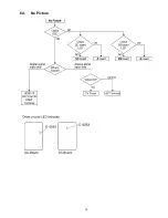
Page 15: ...15 6 4 No Picture...
Page 24: ...24 8 1 4 Adjustment Volume Location 8 1 5 Test Point Location...
Page 26: ...26...
Page 32: ...32...
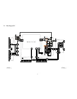
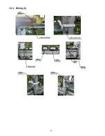
Page 34: ...34 10 3 Wiring 2...
Page 35: ...35 11 Schematic Diagram 11 1 Schematic Diagram Note...
Page 88: ...88 13 1 2 Accessories...
Page 89: ...89 13 1 3 Mechanical Replacement Parts List...
Page 92: ...92 13 2 Electrical Replacement Parts List 13 2 1 Replacement Parts List Notes...

