background image

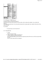
3. To exit the Hotel mode setup menu

Disconnect AC power cord from wall outlet.

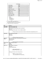
4. Explain the Hotel mode setup menu

Item

Function

Hotel Mode

Select hotel mode On/Off

Initial INPUT

Select input signal modes.

Set the input, when each time power is switched on.

Selection :

Off,Analogue,DVB-C,DVB-T,AV1,AV2,HDMI1,HDMI2

Off: give priority to a last memory. However, Euro model is compulsorily set to TV.

Initial POS

Select programme number.

Selection :

Off/0 to 99

Off: give priority to a last memory.

Initial VOL

LEVEL

Adjust the volume when each time power is switched on.

Selection Range :

Off/0 to 100

Off: give priority to a last memory.

Maximum Vol

Level

Adjust maximum volume.

Range :

0 to 100

Button Lock

Select local key conditions.

Selection :

Off/SETUP/MENU/ALL

OFF: altogether valid

SETUP: only F-key is invalid

(Tuning guide (menu) can not be selected.)

MENU: only F-key is invalid

(only Volume/Mute can be selected.)

Page 3 of 4

12/31/2016

file://C:\Users\sh.dehghani\Desktop\New folder\TH-60AS800SALLSVC_MTV1401275...

Summary of Contents for TH-60AS800S

Page 1: ...ER NO MTV1401275CE LED TV Chassis LA53 Destination SINGAPORE Panasonic Corporation 2014 Model No TH 60AS800S Page 1 of 1 12 31 2016 file C Users sh dehghani Desktop New folder TH 60AS800SALLSVC_MTV1401275 ...

Page 2: ...oubleshooting Guide 7 Disassembly and Assembly Instructions 8 Measurements and Adjustments 9 Block Diagram 10 Wiring Connection Diagram 11 Schematic Diagram 12 Printed Circuit Board 13 Exploded View and Replacement Parts List Page 1 of 1 12 31 2016 file C Users sh dehghani Desktop New folder TH 60AS800SALLSVC_MTV1401275 ...

Page 3: ... cabinet part on the equipment such as screwheads connectors control shafts etc When the exposed metallic part has a return path to the chassis the reading should be 8 5Mohm to 13Mohm When the exposed metal does not have a return path to the chassis the reading must be 1 1 2 Leakage Current Hot Check See Figure 1 1 Plug the AC cord directly into the AC outlet Do not use an isolation transformer fo...

Page 4: ...able conductive material 7 Immediately before removing the protective material from the leads of a replacement ES device touch the protective material to the chassis or circuit assembly into which the device will be installed Caution Be sure no power is applied to the chassis or circuit and observe all other safety precautions 8 Minimize bodily motions when handling unpackaged replacement ES devic...

Page 5: ...lder to double layered boards please check the component side for excess solder which may flow onto the opposite side see figure below Page 2 of 2 12 31 2016 file C Users sh dehghani Desktop New folder TH 60AS800SALLSVC_MTV1401275 ...

Page 6: ...4 STBY EEP Repairable P BOARD Power Supply Repairable GK BOARD Function SW for LGD panel Repairable K BOARD LED RM CATS Repairable LD BOARD LED DRIVER Repairable MD BOARD Motion detection Repairable Page 1 of 1 12 31 2016 file C Users sh dehghani Desktop New folder TH 60AS800SALLSVC_MTV1401275 ...

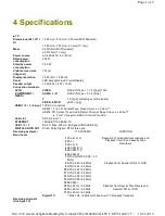
Page 7: ... Colour This TV supports HDAVI Control 5 function Card slot SD Card slot 1 ETHERNET 10BASE T 100 BASE TX USB 1 2 3 DC 5 V Max 500 mA Hi Speed USB USB 2 0 DIGITAL AUDIO OUT PCM Dolby Digital DTS Fibre optic Receiving systems Band name 17 SYSTEMS FUNCTION 1 PAL B G H Reception of broadcast transmissions and Playback from Video Cassette Tape Recorders 2 PAL I 3 PAL D K 4 SECAM B G 5 SECAM D K 6 SECAM...

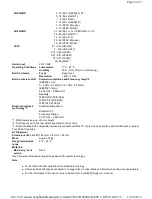
Page 8: ...cus Resolution 1 920 1 080 Built in wireless LAN Standard compliance and Frequency range 2 IEEE802 11a n 5 15 GHz 5 35 GHz 5 47 GHz 5 85 GHz IEEE802 11b g n 2 400 GHz 2 4835 GHz Security WPA2 PSK TKIP AES WPA PSK TKIP AES WEP 64 bit 128 bit Bluetooth wireless technology 3 Standard Compliance Bluetooth 3 0 Frequency Range 2 402 GHz 2 480 GHz 1 With Camera pop up 23 mm height 2 The frequency and cha...

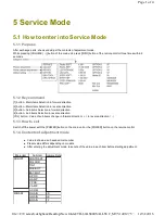
Page 9: ... direction VOL button Value of sub items change in forward direction in reverse direction 5 1 3 How to exit Switch off the power with the POWER button on the main unit or the POWER button on the remote control 5 1 4 Contents of adjustment mode Value is shown as a hexadecimal number Preset value differs depending on models After entering the adjustment mode take note of the value in each item befor...

Page 10: ...ode 1 Purpose Restrict a function for hotels 2 Access command to the Hotel mode setup menu In order to display the Hotel mode setup menu While pressing VOLUME button of the main unit press AV button of the remote control three times within2 seconds Then the Hotel mode setup menu is displayed R CENT 6C G RENT 80 B CENT A0 OPTION Boot ROM STBY SET 00 EMERGENCY ON CLK MODE 00 CLOCK FC7 Y C DELAY DYNA...

Page 11: ...itial POS Select programme number Selection Off 0 to 99 Off give priority to a last memory Initial VOL LEVEL Adjust the volume when each time power is switched on Selection Range Off 0 to 100 Off give priority to a last memory Maximum Vol Level Adjust maximum volume Range 0 to 100 Button Lock Select local key conditions Selection Off SETUP MENU ALL OFF altogether valid SETUP only F key is invalid ...

Page 12: ...eated to store the hotel mode setting in the USB switch OFF the unit pull out USB from unit To copy the hotel mode setting from USB enter hotel mode insert USB choose Copy USB to TV follow instruction as shown on the units once finish switch OFF the unit pull out USB from unit Private Information Select private information for VIERA Cast is Keep or Reset if Hotel mode is set to On when TV power on...

Page 13: ... direction VOL button Value of sub items change in forward direction in reverse direction 5 1 3 How to exit Switch off the power with the POWER button on the main unit or the POWER button on the remote control 5 1 4 Contents of adjustment mode Value is shown as a hexadecimal number Preset value differs depending on models After entering the adjustment mode take note of the value in each item befor...

Page 14: ...ode 1 Purpose Restrict a function for hotels 2 Access command to the Hotel mode setup menu In order to display the Hotel mode setup menu While pressing VOLUME button of the main unit press AV button of the remote control three times within2 seconds Then the Hotel mode setup menu is displayed R CENT 6C G RENT 80 B CENT A0 OPTION Boot ROM STBY SET 00 EMERGENCY ON CLK MODE 00 CLOCK FC7 Y C DELAY DYNA...

Page 15: ...itial POS Select programme number Selection Off 0 to 99 Off give priority to a last memory Initial VOL LEVEL Adjust the volume when each time power is switched on Selection Range Off 0 to 100 Off give priority to a last memory Maximum Vol Level Adjust maximum volume Range 0 to 100 Button Lock Select local key conditions Selection Off SETUP MENU ALL OFF altogether valid SETUP only F key is invalid ...

Page 16: ...eated to store the hotel mode setting in the USB switch OFF the unit pull out USB from unit To copy the hotel mode setting from USB enter hotel mode insert USB choose Copy USB to TV follow instruction as shown on the units once finish switch OFF the unit pull out USB from unit Private Information Select private information for VIERA Cast is Keep or Reset if Hotel mode is set to On when TV power on...

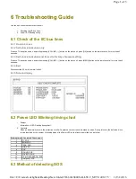
Page 17: ...ote control for more than 3 seconds 6 1 4 Exit Disconnect the AC cord from wall outlet 6 1 5 Screen display 6 2 Power LED Blinking timing chart 1 Subject Information of LED Flashing timing chart 2 Contents When an abnormality occurs the protection circuit will operate and reset the unit to stand by mode During this time the defective block can be identified by the number of blinking times of the P...

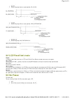
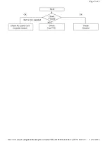
Page 18: ...d go into LCD Panel test mode to display the several test patterns And then judge by the following method Still abnormal picture is displayed The cause must be in LCD Panel Normal picture is displayed The cause must be in A board Remarks The test pattern is created by the circuit in LCD Panel In LCD Panel test mode this test pattern is displayed unaffected by signal processing for RF or input sign...

Page 19: ...Page 3 of 3 12 31 2016 file C Users sh dehghani Desktop New folder TH 60AS800SALLSVC_MTV1401275 ...

Page 20: ...ote control for more than 3 seconds 6 1 4 Exit Disconnect the AC cord from wall outlet 6 1 5 Screen display 6 2 Power LED Blinking timing chart 1 Subject Information of LED Flashing timing chart 2 Contents When an abnormality occurs the protection circuit will operate and reset the unit to stand by mode During this time the defective block can be identified by the number of blinking times of the P...

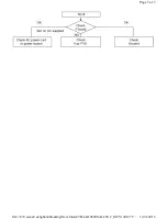
Page 21: ...d go into LCD Panel test mode to display the several test patterns And then judge by the following method Still abnormal picture is displayed The cause must be in LCD Panel Normal picture is displayed The cause must be in A board Remarks The test pattern is created by the circuit in LCD Panel In LCD Panel test mode this test pattern is displayed unaffected by signal processing for RF or input sign...

Page 22: ...Page 3 of 3 12 31 2016 file C Users sh dehghani Desktop New folder TH 60AS800SALLSVC_MTV1401275 ...

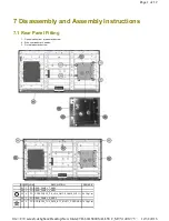
Page 23: ... rear panel and screw NO QTY UOM DESCRIPTION REMARK 01 1 PC REAR_PANEL_T_ASSY 02 1 PC REAR_PANEL_L_ASSY 03 4 PC SCREW A 10_P 6_LD 4_ONC 8_CAM 2_WIFI 1 5 1 Kgf cm 04 1 PC REAR_PANEL_R_ASSY 05 2 PC SCR BC26_TU5_WIFI1_BT1_INLET1_F PEDL R4 7 1 Kgf cm Page 1 of 12 12 31 2016 file C Users sh dehghani Desktop New folder TH 60AS800SALLSVC_MTV1401275 ...

Page 24: ... into the cabinet by taking below precautions Other general precautions 06 1 PC CONDUCTIVE SHEET 07 1 PC HEAT RUBBER 08 1 PC HEAT_RUBBER 35 15 2 5 09 1 PC ORNAMENT_CASE_ASSY 10 1 PC HEATSINK_BOTTOM Page 2 of 12 12 31 2016 file C Users sh dehghani Desktop New folder TH 60AS800SALLSVC_MTV1401275 ...

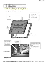
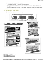
Page 25: ... repellent solvent thiner or other voiltile substances This may degrade surface quality or cause peeling of the paint 5 The surface of the display panel is specially treated and may be easily damaged Take care not to tap or scratch with your fingernail or other hard objects 7 3 Ornament Preparation 1 Insert wire at all board 2 Fix led panel speaker and ir motion sensor at bottom ornament NO QTY UO...

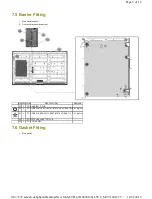
Page 26: ...RIPTION REMARK 01 4 PC VESA METAL 02 8 PC SCREW RP 2 MTL BRKT BTM L R 8 LD BRKT 2 7 1 Kgf cm 03 19 PC SCREW A 10_P 6_LD 4_ONC 8_CAM 2_WIFI 1 5 1 Kgf cm 04 4 PC SCREW VESA 4 MTL BRKT BTM 6 LD BRKT1 6 1 Kgf cm 05 1 PC METAL_BRACKET_BTM_L 06 1 PC METAL_BRACKET_BTM_R 07 1 PC USB_WIRE A WIFI Page 4 of 12 12 31 2016 file C Users sh dehghani Desktop New folder TH 60AS800SALLSVC_MTV1401275 ...

Page 27: ...t NO QTY UOM DESCRIPTION REMARK 01 1 PC BARRIER_P PCB 02 2 PC SCREW RP 2 MTL BRKT BTM L R 8 LD BRKT 2 6 1 Kgf cm 03 1 PC SCREW VESA 4 MTL BRKT BTM 6 LD BRKT1 7 1 Kgf cm 04 1 PC METAL BRACKET LD PCB 05 1 PC LCD_PANEL Page 5 of 12 12 31 2016 file C Users sh dehghani Desktop New folder TH 60AS800SALLSVC_MTV1401275 ...

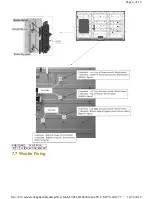
Page 28: ...7 7 Woofer Fixing NO QTY UOM DESCRIPTION 01 1 PC KEY_BUTTON_BRACKET Page 6 of 12 12 31 2016 file C Users sh dehghani Desktop New folder TH 60AS800SALLSVC_MTV1401275 ...

Page 29: ...nt cover L NO QTY UOM DESCRIPTION REMARK 01 1 PC WOOFER 02 3 PC SCREW WOOFER 3 6 1 Kgf cm 03 6 PC SCREW VESA 4 MTL BRKT BTM 6 LD BRKT1 04 2 PC SCREW A 10_P 6_LD 4_ONC 8_CAM 2_WIFI 1 5 1 Kgf cm 05 1 PC THERMAL_CONDUCTIVE_SHEET 12 22 T5 0 06 0 06 MT PET_TAPE Page 7 of 12 12 31 2016 file C Users sh dehghani Desktop New folder TH 60AS800SALLSVC_MTV1401275 ...

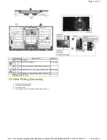
Page 30: ... CAMERA 02 1 PC CAMERA_MODULE 03 1 PC ORNAMENT_COVER_L 04 1 PC FFC A LD 13P 05 1 PC FFC_A TCON_LVDS 51PIN 06 1 PC WIRE A02 P2 07 1 PC FFC_LVDS 41PIN 08 1 PC ORNAMENT_COVER_R 09 1 PC WIRE P6 LD1 10 1 PC LD FFC 24pin UPPER 11 1 PC LD FFC 24pin LOWERS 12 1 PC WIRE P5 GK4 Page 8 of 12 12 31 2016 file C Users sh dehghani Desktop New folder TH 60AS800SALLSVC_MTV1401275 ...

Page 31: ...cover stick label at cover and screw NO QTY UOM DESCRIPTION REMARK 01 1 PC CARTON_BOTTOM 02 3 92 MT PP CATOP2 03 BTM0 88 CUTOPL0 2 BOTR0 81 2 pcs 440 mm Page 9 of 12 12 31 2016 file C Users sh dehghani Desktop New folder TH 60AS800SALLSVC_MTV1401275 ...

Page 32: ...AL ASSY 02 1 PC WIFI_MODULE 03 1 PC AV_INDI_SHEET_SIDE 04 1 PC AV_INDI_SHEET_BTM 05 1 PC KEY_BUTTON_SHEET 06 1 PC AC_CORD 07 1 PC BT_COVER 08 1 PC INLET_COVER 09 6 PC SCREW F_PEDE_L R MTL_BRKT_BTM_L R 6 10 1 Kgf cm 10 3 PC SCREW 6 1 Kgf cm Page 10 of 12 12 31 2016 file C Users sh dehghani Desktop New folder TH 60AS800SALLSVC_MTV1401275 ...

Page 33: ...le by two people and hold on that top and bottom long side by both hands without module warping Never handle the module with keeping horizontal position when moving the module About the work table When tightening a screw retention structures are required not to deform the LCD module Moving the TV Hold the specified parts as shown to stand the TV up and move it with two people Page 11 of 12 12 31 2...

Page 34: ...Page 12 of 12 12 31 2016 file C Users sh dehghani Desktop New folder TH 60AS800SALLSVC_MTV1401275 ...

Page 35: ...PANEL12V TP4000 4001 11 50V 12 50V SUB5V TP5420 4 80V 5 30V USB5V TP5440 5 00V 5 40V SUB3 3V TP5401 3 20V 3 50V SUB1 8V TP8714 1 70V 1 90V SUB1 5V TP8101 1 38V 1 54V SUB1 1V TP8100 1 00V 1 24V HDMI3 3V TP8701 3 16V 3 50V GCX1 5V TP9501 1 38V 1 54V GCX1 1V TP9500 1 10V 1 24V REG_1 8V TP5702 1 70V 1 90V Output Test Point Step 1 Step 2 24V TP7407 1V 24 2 4V 16V TP7410 1V 16 0 8V 5VS TP7501 5 25 0 25V...

Page 36: ...12V LD3 PANEL12V R Digital Audio Signal SD DATA KEY REMOTE RECEIVER SUB_ON SUB3 3V KEY POWER ON NAND_I F P16V DCDC P SOUND_SOS POWER SUPPLY COMP C A T S SENSOR COMPONENT IN BL_ON SUB1 1V POWER CORD STB5V SUB3 3V LED_R G A10 PEAKS PRO4 LAN I F SUB_ON SUB3 3V LDO 3 3V LLC CONVERTER REMOTE RECEIVER OUT DDR3 HDMI3 3V SPI DATA A SPI DATA BL_PWM HDMI I F BL_PWM LED_R G BL_PWM SPI DATA LCD DRIVER K10 LAN...

Page 37: ...6V PHOTO COUPLER CS SAFTY CIRCUIT 14 Q7700 2 IC7550 24 8 3 BL_SOS INPUT DET P 8 COMP Q7555 HSYNC POWER SUPPLY LD3 15 2 5V 4 2 LED SW FB1 12 A17 7 P2 10 7 24 9 JK3101 3 Q7201 Q7203 Q7204 R 4 4 5VS 12 1 24V 5V 9 DO 17 BL_PWM SUB5V IC7401 12 LED SW 5 7 1 1V IC7701 6 1 KEY VSYNC 13 IC5480 10 FB 11 DVDD VCC 4 IC5400 19 PC7301 CLK MAIN LF7105 17 PWMOUT Q7403 4 LCD PANEL CONTROL 1 VOL CONT Q7550 58 PFC H...

Page 38: ...V DECODER 22 IC8457 24 TS IN STB RESET A20 JK4703 POWER_ON HDMI IN JK8602 HP_MUTE RESET HDMI_CEC IC8903 25MHz_CLK Peaks RESET DDC I2C HDMI2 ON SCREEN DISPLAY 25 HDMI_CEC KEY SCAN AMP_STBY DDC_IIC0 EEPROM ARC_OUT 26 JK4704 MON_MUTE POWER_DET 27 HDMI4 SUB 3 3V SENSE CLOCK 16 5V 10 28 5 FORMAT CONVERSION DDC I2C SD DATA A D HDMI_CEC JK4701 IC5000 5VDET0 AGC2 LAN AUDIO OUT PANEL_VCC_ON2 IC8714 CON LVD...

Page 39: ...S SENSOR 25 SUB_AI_3 3V PANEL_TEST_ON 6 26 GCX_1 5V G_LED_ON A15 3 27 LVDS DATA 13 4 28 DDR3 A10 11 7 XOUT PRO4_I2C_0 M08 1 HUM SENSOR GCX 3 LVDS DATA 1 XIN 2 IC2870 LCD 5 1 1V OP AMP 7 GCX_1 1V 6 4 12 IC9100 REMOTE RECEIVER IC9504 14 REMOTE LVDS DATA K10 BT3 3V G_XRST D STB3 3V R_LED_ON LCD CONTROL POWER LED SPI FLASH MAIN D DDR I F A 8 8 C A T S SENSOR GCX_DCDCEN REMOTE RECEIVER POWER LED I2C K ...

Page 40: ...ire dressing 10 2 Wire Dressing 2 1 Stick pet tape for wire dressing NO QTY UOM DESCRIPTION REMARK 01 0 24 MT PET TAPE 60 mm 4 pcs 02 0 88 MT PET TAPE 0 06 5 0 11 4 110 mm 8 pcs Page 1 of 3 12 31 2016 file C Users sh dehghani Desktop New folder TH 60AS800SALLSVC_MTV1401275 ...

Page 41: ...tape for wire dressing NO QTY UOM DESCRIPTION REMARK 01 0 66 MT PET TAPE 60 mm 11 pcs 02 0 33 MT PET TAPE 110 mm 3 pcs 03 2 PC PET AL TAPE Page 2 of 3 12 31 2016 file C Users sh dehghani Desktop New folder TH 60AS800SALLSVC_MTV1401275 ...

Page 42: ...NO QTY UOM DESCRIPTION REMARK 01 0 480 MT PET TAPE 0 06 5 0 11 4 60 mm 8 pcs Page 3 of 3 12 31 2016 file C Users sh dehghani Desktop New folder TH 60AS800SALLSVC_MTV1401275 ...

Page 43: ...Model No TH 60AS800S A Board 1 17 1 38 ...

Page 44: ...Model No TH 60AS800S A Board 2 17 2 38 ...

Page 45: ...Model No TH 60AS800S A Board 3 17 3 38 ...

Page 46: ...Model No TH 60AS800S A Board 4 17 4 38 ...

Page 47: ...Model No TH 60AS800S A Board 5 17 5 38 ...

Page 48: ...Model No TH 60AS800S A Board 6 17 6 38 ...

Page 49: ...Model No TH 60AS800S A Board 7 17 7 38 ...

Page 50: ...Model No TH 60AS800S A Board 8 17 8 38 ...

Page 51: ...Model No TH 60AS800S A Board 9 17 9 38 ...

Page 52: ...Model No TH 60AS800S A Board 10 17 10 38 ...

Page 53: ...Model No TH 60AS800S A Board 11 17 11 38 ...

Page 54: ...Model No TH 60AS800S A Board 12 17 12 38 ...

Page 55: ...Model No TH 60AS800S A Board 13 17 13 38 ...

Page 56: ...Model No TH 60AS800S A Board 14 17 14 38 ...

Page 57: ...Model No TH 60AS800S A Board 15 17 15 38 ...

Page 58: ...Model No TH 60AS800S A Board 16 17 16 38 ...

Page 59: ...Model No TH 60AS800S A Board 17 17 17 38 ...

Page 60: ...Model No TH 60AS800S GK Board 18 38 ...

Page 61: ...Model No TH 60AS800S K Board 19 38 ...

Page 62: ...Model No TH 60AS800S LD Board 1 2 20 38 ...

Page 63: ...Model No TH 60AS800S LD Board 2 2 21 38 ...

Page 64: ...Model No TH 60AS800S MD Board 22 38 ...

Page 65: ...Model No TH 60AS800S P Board 1 3 23 38 ...

Page 66: ...Model No TH 60AS800S P Board 2 3 24 38 ...

Page 67: ...Model No TH 60AS800S P Board 3 3 25 38 ...

Page 68: ...Model No TH 60AS800S A Board Top Component Side 26 38 ...

Page 69: ...Model No TH 60AS800S A Board Bottom Component Side 27 38 ...

Page 70: ...Model No TH 60AS800S GK Board 28 38 ...

Page 71: ...Model No TH 60AS800S K Board 29 38 ...

Page 72: ...Model No TH 60AS800S LD Board Top Component Side 30 38 ...

Page 73: ...Model No TH 60AS800S LD Board Bottom Component Side 31 38 ...

Page 74: ...Model No TH 60AS800S MD Board 32 38 ...

Page 75: ...Model No TH 60AS800S P Board Top Component Side 33 38 ...

Page 76: ...Model No TH 60AS800S P Board Bottom Component Side 34 38 ...

Page 77: ...Model No TH 60AS800S Parts Location 35 38 ...

Page 78: ...Model No TH 60AS800S Packing Exploded View 1 36 38 ...

Page 79: ...Model No TH 60AS800S Packing Exploded View 2 37 38 ...

Page 80: ...Model No TH 60AS800S Packing Exploded View 3 38 38 ...

Reviews: