background image

30

Picture Profiles

<isf Mode Setting>

Switches to “PICTURE MENU” mode display. 

1

Follow steps 1–5 in the previous procedure, 
<Locking and unlocking profiles>. 

2

Select “isf Mode”.

Lock1

Change password

MEMORY1

Off

Off

MEMORY2
MEMORY12

Off

isf Mode

2

  set

1

 select

3

Specify “On” or “Off”. 

4

Exit the menu.

 or 

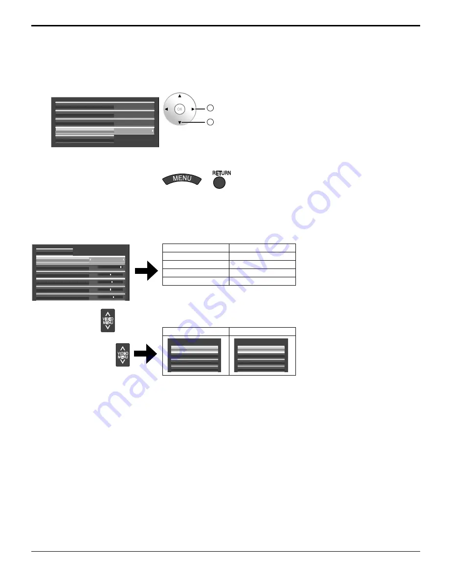
Specifying “On” for isf Mode changes the “PICTURE MENU” mode display as follows. 

“PICTURE menu” mode display

STANDARD

PICTURE MENU

25

0

5

PICTURE

NORMAL IZE

BRIGHTNESS

6

COLOR

0

TINT
SHARPNESS


isf Mode: Off

isf Mode: On

STANDARD

STANDARD

DYNAMIC

isf Mode DAY

CINEMA

isf Mode NIGHT

MONITOR

MONITOR

Mode display when 

 is selected


isf Mode: Off

isf Mode: On

PICTURE MENU

CINEMA

DYNAMIC

STANDARD

MONITOR

PICTURE MENU

isf Mode NIGHT

isf Mode DAY

STANDARD

MONITOR

Summary of Contents for TH-50VX100U

Page 1: ...finition Custom Home Theater Plasma Display TH 50VX100U TH 65VX100U English Before connecting operating or adjusting this product please read these instructions completely Please keep this manual for future reference The illustration shown is an image ...

Page 2: ...let contact an electrician Do not defeat the purpose of the grounding plug This video monitor is designed to display television content from a separate TV tuner Full power analog TV broadcasting in the United States will end as required by law on February 17 2009 after which full power TV broadcasts will be digital only If this device is used after that date to record or display programming from a...

Page 3: ...ent of the obsolete outlet 10 Protect the power cord from being walked on or pinched particularly at plugs convenience receptacles and the point where they exit from the apparatus 11 Only use attachments accessories specified by the manufacturer 12 Use only with the cart stand tripod bracket or table specified by the manufacturer or sold with the apparatus When a cart is used use caution when movi...

Page 4: ... Basic Controls 15 SCROLLING BAR and TEST PATTERNS functions 17 EXT SCALER function 17 ASPECT Controls 18 On Screen Menu Displays 19 PICTURE Adjustments 21 ADVANCED SETTINGS 23 Picture Profiles 25 Saving profiles 26 Loading profiles 27 Editing profiles 28 Locking profiles 29 Adjusting POS SIZE 31 SOUND Adjustment 33 SDI SOUND OUTPUT 33 SCREENSAVER For preventing image retention 34 Reduces screen i...

Page 5: ...g interference that may cause undesired operation FCC CAUTION To assure continued compliance follow the attached installation instructions and use only shielded interface cables when connecting to computer or peripheral devices Any changes or modifications not expressly approved by Panasonic Corp of North America could void the user s authority to operate this device FCC Declaration of Conformity ...

Page 6: ...sulation and cause fire Unplug the cord from the wall outlet and clean it with a dry cloth This Plasma Display radiates infrared rays therefore it may affect other infrared communication equipment Install your infrared sensor in a place away from direct or reflected light from your Plasma Display Note Do not allow a still picture to be displayed for an extended period as this can cause a permanent...

Page 7: ...e pedestal optional accessory leave a space of 3 15 16 10 cm or more at the top left and right and 2 3 4 7 cm or more at the rear and also keep the space between the bottom of the display and the floor surface If using some other setting up method follow the manual of it If there is no specific indication of installation dimension in the installation manual leave a space of 3 15 16 10 cm or more a...

Page 8: ...arbon with Alkaline 4 Do not attempt to charge short circuit disassemble heat or burn used batteries 5 Battery replacement is necessary when the remote control acts sporadically or stops operating the Plasma Display 6 Do not burn or breakup batteries Batteries must not be exposed to excessive heat such as sunshine fire or the like 7 Make a note of the remote control codes before changing batteries...

Page 9: ...g band through the clip as shown in the figure To secure cables connected to Terminals wrap the cable fixing band around them then pass the pointed end through the locking block as shown in the figure While ensuring there is sufficient slack in cables to minimize stress especially in the power cord firmly bind all cables with the supplied fixing band From SERIAL Terminal on Computer see page 11 Fr...

Page 10: ... DDC2B compatible you will need to make setting changes to the computer at the time of connection Some PC models cannot be connected to the set There is no need to use an adapter for computers with DOS V compatible Mini D sub 15P terminal The computer shown in the illustration is for example purposes only Additional equipment and cables shown are not supplied with this set Do not set the horizonta...

Page 11: ...r s 1 5 bytes End 03h STX C1 C2 C3 P1 P2 P3 P4 P5 ETX Notes If multiple commands are transmitted be sure to wait for the response for the first command to come from this unit before sending the next command If an incorrect command is sent by mistake this unit will send an ER401 command back to the computer SL1A SL1B SL2A and SL2B of Command IMS are available only when a dual input terminal board i...

Page 12: ...xample of input signal source Digital TV SET TOP BOX DTV STB HDMI connection This unit has terminal boards equivalent to Dual HDMI Terminal Board TY FB10HMD and RCA Component Video Terminal Board TY 42TM6Z as standard equipment HDMI cables DVD Player or SET TOP BOX HDMI compatible machines only Pin assignments and signal names 19 3 1 4 2 18 Note Additional equipment and HDMI cables shown are not s...

Page 13: ...or Red standby Press the button on the remote control to turn the Plasma Display on Power Indicator Green Turn the power to the Plasma Display off by pressing the switch on the unit when the Plasma Display is on or in standby mode Note During operation of the power management function the power indicator turns orange in the power off state From the second time on the below screen is displayed for ...

Page 14: ...put signal Press to display the menu screen Press to select SET UP Press to display the SET UP menu Press to select OSD LANGUAGE Press to select your preferred language Select the input signals to be connected by installing the optional Terminal Boards Notes Selecting is also possible by pressing the INPUT button on the unit Input terminal will not be selected if the terminal board is not installe...

Page 15: ...utton INPUT1 INPUT2 INPUT3 and PC selection see page 14 Power Indicator The Power Indicator will light Power OFF Indicator not illuminated The unit will still consume some power as long as the power cord is still inserted into the wall outlet Standby Red Power ON Green DPMS Orange With PC input signal and during operation of PC s screensaver MENU Screen ON OFF Each time the MENU button is pressed ...

Page 16: ...ns PC button Press to select PC input see page 14 OK button Press to make selections COMPO button Press to select COMPONENT or RGB input see page 14 DIRECT INPUT buttons Press the each button to select the INPUT mode see page 14 This button is used to switch directly to INPUT mode VIDEO MENU button Press to select PICTURE MENU see page 21 MONITOR STANDARD CINEMA DYNAMIC External equipment operatio...

Page 17: ...lay the following message ON EXTERNAL SCALER MODE Input signal must be 1125p 1080p Note You can also turn the built in scaler ON and OFF by accessing EXTERNAL SCALER MODE in the SET UP menu see page 36 Press YES N O SCROLLING BAR SCROLLING BAR Press to select YES Press Activates the SCROLLING BAR ONLY screensaver After 15 minutes the display enters standby mode SCROLLING BAR ONLY To exit this mode...

Page 18: ... FILL ZOOM FULL JUST 4 3 ZOOM FULL For PC signal input Notes The aspect mode is memorized separately for each input terminal Do not allow the picture to be displayed in 4 3 mode for an extended period as this can cause a permanent image retention to remain on the Plasma Display Panel 4 3 ZOOM JUST FULL For SD signal input 525 480 60i 60p 625 575 50i 50p For HD signal input 1125 1080 60i 50i 60p 50...

Page 19: ...ICTURE NORMAL IZE BRIGHTNESS SHARPNESS COLOR TEMP COLOR MANAGEMENT press MENU press several times Each time the MENU button is pressed the menu screen will switch Normal Viewing PICTURE SET UP POS SIZE SOUND 2 Select the menu SET UP POS SIZE SOUND OPTIONS PICTURE 1 select 2 press Example SOUND menu Menus can also be accessed directly by pressing dedicated buttons such as and see page 21 31 3 Selec...

Page 20: ...E On Onscreen display Off All Aspect Off Studio mode Scrolling bar Function button assign Memory lock CHANNEL 1 LEFT CHANNEL SDI SOUND OUTPUT 2 2 CHANNEL 2 RIGHT CHANNEL ON SOUND OUT OFF LEVEL METER NEGATIVE IMAGE OFF OFF BRIGHT SIDE BAR ADJUST SCREENSAVER START WOBBLING PEAK LIMIT FUNCTION see page 21 30 see page 31 41 see page 31 32 see page 33 see page 42 see page 33 see page 40 41 see page 34 ...

Page 21: ...ICTURE DYNAMIC For viewing in brighter environments This menu selects higher than normal levels of BRIGHTNESS and PICTURE CINEMA Ideal for movies MONITOR For use when creating broadcast or movie content With this picture even if the overall average picture level APL changes the brightness of areas with the same signal level does not change Notes When MONITOR is selected in PICTURE MENU the followi...

Page 22: ...ones NORMAL Intermediate color temperature COOL Colors with a bluish tinge STUDIO Optimal color temperature for studio viewing 3200 K WARM Colors with a reddish tinge WARM NORMAL STUDIO COOL STUDIO can be modified when Studio mode in the OPTIONS menu is On see page 42 COLOR MANAGEMENT OFF ON ON Enables color adjustment automatically Notes COLOR and TINT settings cannot be adjusted for RGB PC input...

Page 23: ...pe of input signal as follows Down Up PICTURE MENU S CURVE 1 0 2 0 2 2 2 5 2 6 STANDARD 3 1 DYNAMIC 3 1 CINEMA 3 2 MONITOR 3 1 When 2k1k signals are received with the Dual Link HD SDI Terminal Board TYFB11DHD GAMMA 2 6 can also be selected 2 When 60 Hz signals are received GAMMA 2 5 can also be selected 3 When 2k1k signals are received with the Dual Link HD SDI Terminal Board TY FB11DHD GAMMA 1 0 ...

Page 24: ... STUDIO GAIN can be modified when Studio mode in the OPTIONS menu is On When Studio mode is Off this setting is OFF and cannot be changed see page 42 This setting is valid only when the input signals are as follows Component Video RGB analog SDI HDMI NOISE REDUCTION Sets the following three NR Noise Reduction functions together VIDEO NR MOSQUITO NR BLOCK NR OFF MID MIN ADVANCED MAX Advanced NR Set...

Page 25: ...LOR MANAGEMENT On Memory lock Onscreen display Scrolling bar Off Off All Aspect Studio mode Function button assign STANDARD ADVANCED SETTINGS PICTURE MENU 25 0 5 OFF NORMAL PICTURE NORMAL IZE BRIGHTNESS 6 COLOR 0 TINT SHARPNESS COLOR TEMP COLOR MANAGEMENT STANDARD ADVANCED SETTINGS PICTURE MENU 0 0 0 OFF NORMAL PICTURE NORMAL IZE BRIGHTNESS 0 COLOR 0 TINT SHARPNESS COLOR TEMP COLOR MANAGEMENT Orig...

Page 26: ...e for the profile Entering profile names Profile names can be up to 16 characters To enter text select characters in the on screen keyboard Edit the default profile name in the text box as desired OK A MEMORY1 MEMORY NAME INPUT B C D E F G H I J K L M ALL DELETE N O P Q R S T U V W X Y Z DELETE SPACE a b c d e f g h i j k l m n o p q r s t u v w x y z 0 1 2 3 4 5 6 7 8 9 _ ˆ CANCEL 1 select 2 OK E...

Page 27: ...elect 2 OK To load profiles 10 16 Example To load profile 16 1 Press The profile number is displayed in the upper right corner of the screen 16 2 Select OK OK CANCEL MEMORY LOAD LOAD FROM MEMORY16 1 select 2 OK Lock1 Picture adjustment values are shown Lock2 Picture adjustment values are hidden PICTURE MENU DYNAMIC 25 0 5 OFF NORMAL PICTURE NORMAL IZE BRIGHTNESS SHARPNESS COLOR TEMP COLOR MANAGEME...

Page 28: ...ct 4 Select Ok OK CANCEL MEMORY DELETE DELETE THE MEMORY1 DATA 1 select 2 OK 1 In the PICTURE menu select MEMORY EDIT MEMORY SAVE MEMORY LOAD MEMORY EDIT 2 OK 1 select 2 Select MEMORY NAME CHANGE MEMORY NAME CHANGE MEMORY DELETE 2 OK 1 select 3 Select the profile to rename 1 MEMORY1 MEMORY2 2 MEMORY12 12 2 OK 1 select 4 Enter a name for the profile Entering profile names page 26 OK A MEMORY NAME I...

Page 29: ...profiles 1 Display the menu screen 2 Select OPTIONS and hold for 3 seconds or more SET UP POS SIZE SOUND OPTIONS PICTURE 2 OK 3seconds ormore 1 select 3 Select Memory lock On Memory lock Onscreen display Scrolling bar Off Off All Aspect Studio mode Function button assign 2 OK 1 select 4 Enter a 4 digit password The default password is 0123 5 Select OK OK CANCEL Input password 1 select 2 OK 6 Selec...

Page 30: ... Off 4 Exit the menu or Specifying On for isf Mode changes the PICTURE MENU mode display as follows PICTURE menu mode display STANDARD PICTURE MENU 25 0 5 PICTURE NORMAL IZE BRIGHTNESS 6 COLOR 0 TINT SHARPNESS isf Mode Off isf Mode On STANDARD STANDARD DYNAMIC isf Mode DAY CINEMA isf Mode NIGHT MONITOR MONITOR Mode display when is selected isf Mode Off isf Mode On PICTURE MENU CINEMA DYNAMIC STAND...

Page 31: ...utomatically In such case press AUTO SETUP again after changing the image to the clearer one When DVI D is input CLOCK PHASE cannot be adjusted automatically Select NORMALIZE in POS SIZE and press the OK button when appropriate adjustment cannot be made H POS Adjust the horizontal position V POS Adjust the vertical position H SIZE Adjust the horizontal size V SIZE Adjust the vertical size 1 Displa...

Page 32: ...LEFT ON CENTER ON RIGHT Note 2k1k signals can only be received when the Dual Link HD SDI Terminal Board TY FB11DHD is installed DISPLAY SIZE Adjusts the image display size on screen OFF Sets the normal image display size on screen ON Sets the image display size approximately 95 of the normal image display OFF ON Notes DISPLAY SIZE can be modified when Studio mode in the OPTIONS menu is On When Stu...

Page 33: ...ANNEL CHANNEL 1 to CHANNEL 16 Selects right audio channel SOUND OUT ON OFF ON Enables audio output OFF Disables audio output LEVEL METER OFF 1 8CH 9 16CH Sets audio channels to show in the audio level meter 8 channels are displayed in the audio level meter 4 channels each on both right and left sides of the display OFF Hides the audio level meter 1 8CH Displays the audio level meter 1 8ch 9 16CH D...

Page 34: ...CROLLING BAR ONLY OVERLAY SCROLLING BAR NEGATIVE IMAGE WHITE SCREEN NEGATIVE IMAGE A negative image will be displayed on the screen SCROLLING BAR ONLY A white bar will scroll from left to right The image won t be displayed OVERLAY SCROLLING BAR The brightness of the image will be decreased and a white bar will scroll on it WHITE SCREEN The whole screen will be white 5 START setting Select START NE...

Page 35: ...ome slightly darker see page 45 Reduces screen image retention SIDE BAR ADJUST Do not display a picture in 4 3 mode for an extended period as this can cause an image retention to remain on the side bars on either side of the display field To reduce the risk of such an image retention illuminate the side bars This function may be applicable to the non picture area Notes To reduce the occurrence of ...

Page 36: ...t in scaler ON Use an external scaler Note Selecting ON in this setting deactivates the following settings and disables these operations POS SIZE menu H SIZE V SIZE 1 1 PIXEL MODE DISPLAY SIZE see page 31 32 PICTURE menu BRIGHTNESS COLOR TINT SHARPNESS MEMORY SAVE MEMORY LOAD see page 22 26 27 ADVANCED SETTINGS 3 2 PULLDOWN NOIZE REDUCTION see page 24 SIGNAL menu XGA MODE see page 40 OPTIONS menu ...

Page 37: ...turned ON power consumption of the microcomputer is reduced during power supply standby see page 13 15 16 so standby power of the set is reduced POWER MANAGEMENT When this function is set to ON it operates under the following conditions to turn the power on or off automatically When no pictures HD VD sync signals are detected for 30 or so seconds during PC IN signal input Power is turned off stand...

Page 38: ...LANGUAGE ENGLISH US 2 change 1 select TYPE1 TYPE2 TYPE3 4 Specify the display position Select OSD POSITION and choose the display position STANDBY SAVE POWER MANAGEMENT AUTO POWER OFF OFF OFF ON OSD DESIGN TYPE1 OSD POSITION UPPER LEFT OSD LANGUAGE ENGLISH US 2 change 1 select Each time you press or the on screen menu display position changes Display example UPPER LEFT CENTER 5 Exit the menu or CO...

Page 39: ...nals RGB Notes Selection may not be possible depending on which optional board is installed Make setting of the selected input terminal SLOT1 or SLOT2 1 Display the menu screen 2 Select SET UP SET UP POS SIZE SOUND PICTURE 2 OK 1 select 3 Select COMPONENT RGB IN SELECT and set COMPONENT RGB IN SELECT EXTERNAL SCALER MODE POWER SAVE OFF OFF RGB SCREENSAVER SIGNAL 2 change 1 select COMPONENT RGB 4 E...

Page 40: ...en the input signal is analog Component PC This unit supports three types of XGA signals with 60Hz vertical frequency having different aspect ratios and sampling rates 1 024 768 60Hz 1 280 768 60Hz and 1 366 768 60Hz Be sure to make settings in accordance with the input signal in order to achieve a more appropriate and attractive display In addition after making this setting be sure to make each a...

Page 41: ...al of Composite Sync input which is input from the HD connector Displays the frequency and the type of the current input signal This display is valid only for COMPONENT RGB PC and Digital input signal Display range Horizontal 15 110 kHz Vertical 48 120 Hz Input signal display The dot clock frequency is displayed during digital signal input Set the active through function of the Dual Link HD SDI Te...

Page 42: ...d OFF Cannot be specified set to OFF and cannot be changed DISPLAY SIZE Can be switched ON and OFF Cannot be specified set to OFF and cannot be changed Function button assign Specifies the function activated when the button on the remote control is pressed Scrolling bar Activates the SCROLLING BAR ONLY screensaver After 15 minutes the display enters standby mode Test patterns Each time you press a...

Page 43: ... see page 44 1 Select the input mode see page 14 HDMI1 HDMI2 HDMI3 HDMI4 COMPONENT PC INPUT INPUT 2 Select the remote control mode Press the key to select DISPLAY VCR DBS CBL DVD 3 Operate the connected equipment pointing Display s remote control at the equipment Example VCR MODE DVD MODE VCR Record Record Skip Reverse Forward Rewind Fast Forward Reverse Forward Stop Stop Pause Pause Play Play For...

Page 44: ...AY If the equipment does not operate with the remote control When your equipment has a single code Input the remote control code again When your equipment has multiple codes Change the code with 4 above and test again Note Registration will fail if the wrong code is input or it takes more than 30 seconds to register To find a code not listed in the code list This procedure searches all codes and i...

Page 45: ...ence a slight time lag may occur between image and audio depending on the type of input signal However this is not a malfunction Plasma Display panel Symptoms Check The screen darkens slightly when bright pictures with minimal movements are shown The screen will darken slightly when photos still images of a computer or other pictures with minimal movements are shown for an extended period This is ...

Page 46: ...e areas around the left and right edges of the screen is slightly elongated 4 3 4 3 Pictures with a 4 3 aspect ratio are displayed with their original aspect ratio Side panels are displayed at the left and right edges of the screen 4 3 1 4 3 2 4 3 Pictures with a 4 3 aspect ratio are displayed with their original aspect ratio The left and right edges of the pictures are masked by side panels 4 3 F...

Page 47: ...which keys are operational after programming if needed while in the selected remote control mode CABLE DBS VCR or DVD KEY NAME VCR MODE DBS CBL MODE DVD MODE DBS CBL Power Power Power Power Menu Menu Functions PPV VOD PPV VOD Return Up Down Left Right Up Down Left Right Up Down Left Right Select Select Enter INPUT CH Channel Up Down Channel Up Down Channel Up Down Channel Up Down 0 9 0 9 0 9 0 9 P...

Page 48: ...onic 0037 Emerex 0032 Emerson 0000 0002 0037 0043 0121 0184 0209 0278 0479 0593 1278 1479 1593 Fisher 0047 0104 Fuji 0033 0035 Funai 0000 0593 1593 Garrard 0000 Gateway 1972 GE 0035 0060 0240 0807 1035 1060 Go Video 0432 0614 GoldStar 0037 0038 1237 Gradiente 0000 Harley Davidson 0000 Harman Kardon 0038 0081 Harwood 0072 Hewlett Packard 1972 HI Q 0047 Hitachi 0000 0041 0042 0089 Howard Computers 1...

Page 49: ...9 LiteOn 1058 1158 1416 1440 Loewe 0511 0885 Magnavox 0503 0539 0646 0675 0821 1268 Malata 0782 1159 Marantz 0539 Memorex 0695 0831 1270 Microsoft 0522 1708 Mintek 0717 0839 Mitsubishi 0521 1521 Momitsu 1082 NAD 0741 NEC 0785 Nesa 0717 Next Base 0826 NexxTech 1402 Norcent 0872 1003 1107 1265 Onkyo 0503 0627 0792 OptoMedia Electronics 0896 Oritron 0651 Panasonic 0490 0703 1362 1462 1490 1762 1779 2...

Page 50: ...768 70 Hz 56 48 70 07 75 0 33 1 024 768 75 Hz 60 02 75 03 78 75 34 1 024 768 85 Hz 68 68 85 00 94 5 35 1 066 600 60 Hz 37 64 59 94 53 0 53 0 36 1 152 864 60 Hz 53 70 60 00 81 62 37 1 152 864 75 Hz 67 50 75 00 108 0 38 1 280 768 60 Hz 47 70 60 00 80 14 39 1 280 960 60 Hz 60 00 60 00 108 0 40 1 280 960 85 Hz 85 94 85 00 148 5 41 1 280 1 024 60 Hz 63 98 60 02 108 0 108 0 42 1 280 1 024 75 Hz 79 98 75...

Page 51: ...27 00 720 858 480 525 3 625 50p 50 00 31 25 27 00 720 864 576 625 4 750 60p 60 00 45 00 74 25 1280 1650 720 750 5 750 50p 50 00 37 50 74 25 1280 1980 720 750 6 1125 60i 60 00 33 75 74 25 1920 2200 1080 1125 7 1125 50i 50 00 28 13 74 25 1920 2640 1080 1125 8 1125 60p 60 00 67 50 148 50 1920 2200 1080 1125 9 1125 50p 50 00 56 26 148 50 1920 2640 1080 1125 10 1125 24p 24 00 27 00 74 25 1920 2750 1080...

Page 52: ...XGA compressed Horizontal scanning frequency 15 110 kHz Vertical scanning frequency 48 120 Hz Connection terminals HDMI A B TYPE A Connector 4 COMPONENT RGB IN Y G RCA PIN JACK PB B PR R RCA PIN JACK AUDIO IN RCA PIN JACK 2 with sync 1 0 Vp p 75 Ω 0 7 Vp p 75 Ω 0 5 Vrms PC IN HIGH DENSITY MINI D SUB 15PIN B PB CB R PR CR HD VD AUDIO IN M3 JACK Y or G with sync 1 0 Vp p 75 Ω Y or G without sync 0 7...

Page 53: ...s indicated above Panasonic Professional Display Company referred to as the Warrantor will repair this product and all included accessories with new or refurbished parts free of charge in the USA or Puerto Rico of the original purchase in the event of a defect in materials or workmanship as follows In the USA and Puerto Rico FOR SERVICE CALL TOLL FREE 1 800 973 4390 2 Years 2 Years On site or carr...

Page 54: ...rage period Proof of product purchase is a condition of warranty service The owner must produce the product purchase receipt or other satisfactory evidence of date of original purchase This warranty does not apply to external appearance items such as handles knobs safety windows etc This warranty does not apply to any part or parts of the product installed altered repaired or misused in any way th...

Page 55: ...55 ...

Page 56: ...500 Dallas Region 6226 Abington Way Houston TX 77008 713 802 2726 No CA Northwest Region 5870 Stone Ridge 3 Pleasanton CA 925 416 5108 Government Marketing Department 52 West Gude Drive Rockville MD 20850 301 738 3840 Panasonic Canada Inc 5770 Ambler Drive Mississauga Ontario L4W 2T3 Customer s Record The model number and serial number of this product can be found on its back cover You should note...

Reviews: