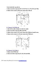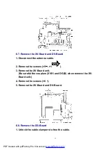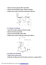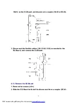
3. Disconnect the flexible cables (D33 and D34).
4. Remove the screws (×4 ) and remove the D-Board.
6.5. Remove the rear terminal cover
1. Remove the screws (×4 , ×7 , ×2
).
2. Remove the rear terminal cover.
6.6. Remove the metal frame
1. Unlock the cable clampers to free the cable.
2. Disconnect the couplers (D3, D5, H7, P10 and PB7) and relay
connector (SP-R, SP-L).
3. Remove the screws (×5 ) remove the metal frame.
10
PDF created with pdfFactory Pro trial version
Summary of Contents for TH-42PE55E
Page 22: ...22 PDF created with pdfFactory Pro trial version www pdffactory com ...
Page 29: ...9 3 Option Description 29 PDF created with pdfFactory Pro trial version www pdffactory com ...
Page 30: ...30 PDF created with pdfFactory Pro trial version www pdffactory com ...
Page 49: ...49 PDF created with pdfFactory Pro trial version www pdffactory com ...
Page 51: ...51 PDF created with pdfFactory Pro trial version www pdffactory com ...
Page 129: ...14 Block and Schematic Diagram 14 1 Schematic Diagram Notes 67 ...
Page 130: ...14 Block and Schematic Diagram 14 1 Schematic Diagram Notes 67 ...


