background image

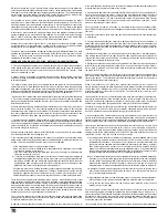
67

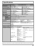
RGB input

D-SUB 15pin

R,G,B / 0.7 Vp-p (75 

)

HD, VD / 1.0 - 5.0 Vp-p (high impedance)

AV INPUT 1- 3

VIDEO

1.0 Vp-p (75 

)

(Phono Jack Type)

S-VIDEO

Y : 1.0 Vp-p (75 

), C : 0.286 Vp-p (75 

)

(Mini DIN 4-pin)

AUDIO L-R

0.5 Vrms

(Phono Jack Type 

×

 2)

AV  PROG. OUT

VIDEO

1.0 Vp-p (75 

)

(Phono Jack Type)

AUDIO L-R

0.5 Vrms

(Phono Jack Type 

×

 2)

TO AUDIO AMP

AUDIO L-R

0.5 Vrms

(Phono Jack Type 

×

 2)

COMPONENT VIDEO

Y

1.0 Vp-p (including synchronization)

INPUT1-2

P

B

 / P

R

±

 0.35 Vp-p

AUDIO L-R

0.5 Vrms

(Phono Jack Type 

×

 2)

HDMI

HDMI type A Connector
AUDIO L-R

0.5 Vrms

(Phono Jack Type 

×

 2)

DIGITAL AUDIO OUT

PCM / Dolby Digital, Fiber Optic

Note:

 Design and Specifications are subject to change without notice. Weight and Dimensions shown are approximate.

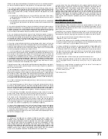
Specifications

Power Source

Power Consumption

Plasma Display panel

Screen Size

Channel Capability-ATSC/NTSC

VHF/ UHF : 2-69, CATV:1-136

Operating Conditions

Temperature : 34 

°

F - 104 

°

F (0 

°

 –  40 

°

C)

Humidity : 20 % - 80 % (non-condensing)

Connection Terminals

Speaker

Woofer 

φ

1.57 ” (40 mm) 

×

 8 , Tweeter 

φ

1.38 ” (35 mm) 

×

 2

Audio Output

Headphone

M3 (3.5 mm) Jack 

×

 1

Sound

16 W  [ 8 W + 8 W ]  ( 10 % THD )

FEATURES

Two screen display fuctions

3D Y/C FILTER

HDMI

BBE VIVA 3D

LINEAR PIP

JPEG Viewer

CLOSED CAPTION

V-Chip

Accessories Supplied

Remote control: EUR7627Z10

Ferrite cores : large 

×

 4, small 

×

 6

AA Battery 

×

 2

F-type antenna adapter (3C-2V 

×

 2, 5C-2V 

×

 2)

AC Cord
Pedestal
Fixing band

Dimensions
( W 

×

 H 

×

 D )

Mass (Weight)

TH-37PD25

TH-42PD25

Maximum : 345 W
Stand-by condition : 18 W

Drive method : AC type 37-inch ,

16 : 9 aspect ratio

32.20 ” (818 mm) (W) 

×

18.15 ” (461 mm) (H) 

×

36.97 ” (939 mm) (diagonal)

42.13 ” (1070 mm)  

×

23.46 ” (596 mm)  

×

3.90 ” (99 mm)

67.2 lb. (30.5 kg) Net

AC 120 V, 50/60 Hz

Maximum : 395 W
Stand-by condition : 18 W

Drive method : AC type 42-inch ,

16 : 9 aspect ratio

36.22 ” (920mm) (W) 

×

20.39 ” (518 mm) (H) 

×

41.57 ” (1056 mm) (diagonal)
46.06 ” (1170 mm)  

×

29.91 ” (658 mm)  

×

3.90 ” (99 mm)

79.4 lb. (36.0 kg) Net

Summary of Contents for TH-42PD25U/P

Page 1: ...e call 1 888 VIEW PTV 843 9788 or send e mail to consumerproducts panasonic com or visit us at www panasonic com U S A For assistance please call 787 750 4300 or visit us at www panasonic com Puerto Rico TV POWER MENU R TUNE PIP MIN REW PIP MAX FF PLAY PROG EXIT VCR DVD DBS RCVR CBL LIGHT TV VIDEO A ANTENNA B SAP 1 2 3 4 5 6 7 8 0 9 AUX ASPECT M U T E RE C A L L BBE STOP PAUSE FREEZE TV VCR PIP SP...

Page 2: ...rks of BBE Sound Inc This product incorporates copyright protection technology that is protected by U S patents and other intellectual property rights Use of this copyright protection technology must be authorized by Macrovision Corporation and is intended for home and other limited viewing uses only unless otherwise authorized by Macrovision Reverse engineering or disassembly is prohibited U S Pa...

Page 3: ...ot defeat the safety purpose of the polarized or grounding type plug A polarized plug has two blades with one wider than the other A grounding type plug has two blades and a third grounding prong The wide blade or the third prong are provided for your safety If the provided plug does not fit into your outlet consult an electrician for replacement of the obsolete outlet 10 Protect the power cord fr...

Page 4: ...come to the Panasonic family of customers We hope that you will have many years of enjoyment from your new Plasma TV To obtain maximum benefit from your set please read these Instructions before making any adjustments and retain them for future reference Retain your purchase receipt also and record the model number and serial number of your set in the space provided on the back cover of these inst...

Page 5: ...e FCC Rules Operation is subject to the following two conditions 1 This device may not cause harmful interference and 2 this device must accept any interference received including interference that may cause undesired operation FCC CAUTION To assure continued compliance and possible undesirable interference the provided ferrite cores must be used when connecting this plasma television to video equ...

Page 6: ...23 VHF and UHF 23 Cable TV 23 Menu Navigation 24 Picture 26 Pic Mode 26 Color Tint Brightness Picture Sharpness Normal 26 Other Adjust 26 Audio 28 Bass Treble Balance Normal 28 Other Adjust 28 Channel 30 Favorite 30 Captions 31 Timer 33 Sleep 33 Timer 34 Clock Set 35 Day Set 35 Setup 36 Program CH 36 Auto Scan 37 Manual Program 37 Closed Caption 39 Other Adjust 41 CableCARD 41 Lock 42 Password 42 ...

Page 7: ...enerated which could cause fire If the plug is damaged or the wall socket plate is loose they should not be used Do not handle the power cord plug with wet hands Doing so may cause electric shocks Do not do anything that might damage the power cable When disconnecting the power cable hold the plug not the cable Do not make any modifications place heavy objects on place near hot objects heat bend t...

Page 8: ... it may affect other infrared communication equipment Install your infrared sensor in a place away from direct or reflected light from your Plasma TV Cleaning and maintenance The front of the display panel has been specially treated Wipe the panel surface gently using only a cleaning cloth or a soft lint free cloth If the surface is particularly dirty soak a soft lint free cloth in a weak detergen...

Page 9: ...o cables For best performance video cables should utilize 75 ohm coaxial shielded wire Cables are available from your dealer or electronic supply store Before you purchase any cables be sure you know what type of output and input connectors your various components require Also determine the length of cable you will need Installation Receiver Location This unit is intended to be used with an option...

Page 10: ...Remote control EUR7627Z10 Warranty card Fixing band AC cord Batteries for the remote control AA Battery 2 Pedestal TY ST42PA20 Customer card Service center list Customer care plan card Large size 4 Attaching the ferrite core Be sure to choose the appropriate size of ferrite core large or small and the correct setting of the cable winding or passing as indicated by each connection diagram on the fo...

Page 11: ...als see pages 12 13 HDMI terminal see page 14 COMPONENT Input terminals see page15 AV terminals see pages 15 16 Cable fixing bands Secure cables connected to terminals with bands as required Wrap the cable fixing band around cables then pass the pointed end through the locking block as shown in the figure While ensuring there is sufficient slack in cables to minimize stress especially in the power...

Page 12: ...ning the correct antenna system for your particular area and the accessories required Any matters regarding antenna installation upgrading of existing systems or accessories required and the costs incurred are your responsibility VHF antenna UHF antenna Mixer 75 Ohm coaxial cable Antenna Connection Ferrite core large size supplied F Type Antenna Adapter supplied Less than 4 10 cm For proper recept...

Page 13: ...your cable company on the availability of CableCARD CableCARD Connection B A ANTENNA SERVCE ONLY DIGITAL AUDIO OUT CABLE CARD Cable In IN S E R T T H IS E N D P O D M O D U L E Back of the TV Upper side of the card Notes If you experience keyboard or remote control function hang up when using CableCARD unplug the TV and plug it back on and try the controls again If this condition still exists plea...

Page 14: ...e 3 to connect to the HDMI terminal Connect the audio cables to the AUDIO IN terminals for HDMI Select the audio setting in HDMI In see page 29 Notes This input terminal is not intended for use with computers 1080i signals will be re formatted to view on your plasma display Notes This HDMI connector is Type A If you connect an equipment without a digital output terminal connect to the COMPONENT VI...

Page 15: ...DTV STB Digital TV Set Top Box or DVD Player Digital TV Set Top Box DTV STB or DVD Connection DIGITAL TV OUTPUT MAIN VIDEO AUDIO OUTPUT PB PR Y R L PROG OUT COMPONENT VIDEO INPUT S VIDEO VIDEO Y PB L R PR 1 2 1 2 INPUT VIDEO TO AUDIO AMP Back of the TV Set Top Box DVD player Component Video cable Audio cable VCR Connection S Video cable Video cable Audio cable Back of the TV VCR PROG OUT COMPONENT...

Page 16: ...ired level Optical digital audio cable Audio cable Amplifier For a full Home Theater sound experience an external Dolby Digital decoder and a multichannel amplifier must be connected to the DIGITAL AUDIO OUT terminal on the TV Dolby Digital 5 1 channel surround sound delivers digital quality sound Dolby Digital provides five discrete full bandwidth channels for front left front right center surrou...

Page 17: ...t Audio Video input terminals Connecting to the front AV terminals A second VCR video disc player video game equipment and DSS equipment can also be connected to the video input terminals See the optional equipment manual for details Note The S VIDEO connection provides higher quality picture It overrides other VIDEO connections Use INPUT 3 AUDIO L and R with S VIDEO connection CAMCORDER Ferrite c...

Page 18: ...n is for example purposes only 6 Additional equipment and cables shown are not supplied with this set 7 Do not set the horizontal and vertical scanning frequencies for PC signals which are above or below the specified frequency range PC S VIDEO VIDEO INPUT 3 L AUDIO R Signal Names for D sub 15P Connector Pin Layout for PC Input Terminal Pin No 1 2 3 4 5 Signal Name R G B NC not connected GND Groun...

Page 19: ... Unit S VIDEO PC CHANNEL VOLUME MENU OK HPJ VIDEO VIDEO3 L AUDIO R SD CARD PUSH EJECT POWER POWER S VIDEO PC CHANNEL VOLUME OK MENU TV VIDEO HPJ VIDEO INPUT3 L AUDIO R SD CARD PUSH EJECT POWER button OK Choose menu and submenu entry Volume adjusters C A T S sensor Plasma C A T S Contrast Automatic Tracking System automatically senses the ambient light conditions and adjusts the brightness and grad...

Page 20: ...s Mode Selection buttons see page 59 Location of Controls TV TV VCR VCR DVD DVD DBS Digital Broadcasting Satellite RCVR Receiver Amplifier CBL Cable TV AUX Aux PIP MIN REW PIP MAX FF PLAY STOP PAUSE FREEZE TV VCR SEARCH OPEN CLOSE PIP CH DVD VCR CH REC PIP MIN PIP MAX Change the size of PIP frame see page 52 Operation of other Device see pages 63 64 SEARCH Display search frames during PIP or SPLIT...

Page 21: ...er Rating Clock Program Aspect Picture mode setting PIP SPLIT CH number or Input information Closed Caption SAP indication Time remaining in Sleep Timer Press OK button to add or delete the channel in the Favorite channel list see page 30 LIGHT Light the remote control buttons The selected button blinks when lit A ANTENNA B Switch to A or B RF antenna input BBE Turn BBE VIVA 3D OFF or ON see page ...

Page 22: ...n is pressed at anytime during Auto Scan Auto Scan will be cancelled and the TV will return to the First Time Setup menu If a CableCARD is present during the First Time Setup and Antenna A is set to cable Antenna A will not be scanned due to the CableCARD providing the channel map First Time Setup Input Setup Cable Antenna Auto Scan Setting 1 2 CH VOL CH VOL OK CH VOL CH VOL OK Press to select the...

Page 23: ...me level POWER Notes The channel number and volume level remain the same even after the TV is turned off Power consumption and howling sound can be reduced if the volume level is lowered TV CH VOL CH VOL OK CH VOL CH VOL OK Cable TV 1 Select the TV channel 3 or 4 2 Press to operate the cable box with the remote control 3 Press to turn the cable box on CH VOL CH VOL OK Point the remote control towa...

Page 24: ...Other Adjust Pic Mode Vivid 31 31 26 63 50 No ex Picture menu About The About screen displays assorted information about the TV Please have this information when calling Customer Care Center TV POWER R TUNE PIP MIN REW PIP MAX FF PLAY PROG VCR DVD DBS RCVR CBL LIGHT TV VIDEO A ANTENNA B SAP 1 2 3 4 5 6 7 8 0 9 AUX ASPECT M U T E RE C A L L BBE STOP PAUSE FREEZE TV VCR PIP SPLIT MOVE SWAP SEARCH OP...

Page 25: ...ss to return To return to the previous screen Press to return to normal picture To exit menus MENU EXIT Menu Navigation 1 CH VOL CH VOL OK 2 Press to select the sub menu Press to select or activate the sub menu Other Adjust Natural Color Video NR 3D Y C Filter Color Matrix Freeze Color Temp Cool Split On Off Off HD ...

Page 26: ...emp setting see page 27 Note Each mode has its own picture settings Color Tint Brightness Picture and Sharpness 1 Press to select Other Adjust Press to display the sub menu CH VOL CH VOL OK 2 Press to select the sub menu Press to select or activate the sub menu Other Adjust Natural Color Video NR 3D Y C Filter Color Matrix Freeze Color Temp Cool Split On Off Off HD Menu Navigation Picture Picture ...

Page 27: ...3D Y C Filter To increase or decrease Warm red and Cool blue colors to suit personal preferences To increase the color reproduction range with natural color gradation and highly delicate hues Reduces noise in the channel commonly called snow Remains off when receiving a strong signal Minimizes noise and cross color in the picture Color Temp temperature Natural Color Video NR 3D Y C Filter Color Ma...

Page 28: ...le Balance Normal Increase or decrease the bass response Increase or decrease the treble response Emphasize the left right speaker volume Reset Bass Treble and Balance adjustments to factory default settings Menu Navigation Audio Treble Balance Normal Other Adjust Bass 7 7 31 Set CH VOL CH VOL OK AI Sound Equalize overall volume levels across all channels AI sound is not available in VIDEO input m...

Page 29: ...E VIVA 3D is set to Off Surround Enhances audio response when listening to stereo Speakers This feature is used to turn TV speakers On or Off see page 16 Amplifier Connection HDMI In When using HDMI see page 14 this feature will let you switch between Analog Input and Digital Input BBE VIVA 3D BBE BBE VIVA 3D BBE VIVA 3D provides a musically accurate natural 3D image with hi fi sound The clarity o...

Page 30: ...o 16 favorite channels 2 Press to select RF Input Press to select Antenna A or Antenna B Press to enter your selection CH VOL CH VOL OK CH VOL CH VOL OK Allows you to create Favorite channel list from Antenna A or Antenna B CH VOL CH VOL OK Menu Navigation Surf Mode RF Input Channel CH VOL CH VOL OK Favorite Surf Mode All Channels RF Input Antenna A Channel A 2 The maximum is 16 favorite channels ...

Page 31: ...et caption 1 2 3 4 5 6 7 8 0 9 CH VOL CH VOL OK Antenna A Preset Labels Manual Labels Input Labels NBC PBS CNN RF Input ABC CBS FOX ESPN HBO Captions 2 Press to select RF Input Press to select Antenna A or Antenna B Press to enter your selection CH VOL CH VOL OK 5 Press to enter your selection To delete a channel number while highlighted press repeatedly until all numbers are removed then press OK...

Page 32: ...cters can be added for each channel To delete the Channel Caption press until no character is displayed Press to enter your selection Note Only input with signal will be selectable 2 Press to select RF Input Press to select Antenna A or Antenna B Press to enter your selection CH VOL CH VOL OK CH VOL CH VOL OK CH VOL CH VOL OK CH VOL CH VOL OK Antenna A A 2 Preset Labels Manual Labels Input Labels ...

Page 33: ...ter your selection CH VOL CH VOL OK CH VOL CH VOL OK Preset Labels Manual Labels Input Labels Video 2 Video 3 PC Component 1 Component 2 HDMI Video 1 Captions Menu Navigation Timer Set the time in Clock Set see page 35 before setting Timer Press to select Sleep Press to select the desired sleep time No 30 60 or 90 To turn off the timer select No To confirm the remaining time press RECALL button se...

Page 34: ...off timer will be deactivated and the TV will be in standby mode even after power is restored CH VOL CH VOL OK Set Select timer to turn the TV on and off at selected times and on selected day Press to select Timer Press to enter the Timer sub menu Press to select Day Press to select appropriate day setting Press to select On Time or Off Time Press to enter the time field 1 CH VOL CH VOL OK CH VOL ...

Page 35: ...nter the time field Press to select Day Set Press to select the day of the week Set the day of the week CH VOL CH VOL OK CH VOL CH VOL OK MENU Press to select the hour AM or PM or the minutes position Press to set the hour AM or PM and the minutes 2 CH VOL CH VOL OK Menu Navigation Clock Set Day Set Press to enter your selection 3 CH VOL CH VOL OK ...

Page 36: ...tart Auto Scan Notes Auto scan is necessary when you select the input signal for the first time or whenever you change the antenna configuration If CableCARD is not inserted theAuto scan performs ScanAll When CableCARD is inserted and Cable only is selected Auto Scan will be skipped When CableCARD is inserted and Cable Antenna is selected Antenna B Analog Digital Auto Scan will be performed In ord...

Page 37: ...A Analog Antenna A Analog Digital Antenna B Analog Antenna B Analog Digital Auto Scan Manual Program Signal Meter Input Setup Antenna A Auto Scan RF Input A 1 A 2 Channel Add Channel Del Manual Program Signal Meter Program Channel To add or delete channels from either channels list A B manually Press to select Manual Program Press to enter the sub menu field 2 CH VOL CH VOL OK Press to select RF I...

Page 38: ... the received signal Green Adequate signal for a good reception Yellow Poor signal strength Red Very poor signal strength 2 Input Setup Antenna B Auto Scan B 26 3 Channel Manual Program Signal Meter Program Channel Signal Strength 96 Peak 96 RF Input CH VOL CH VOL OK Menu Navigation Signal Meter For digital channels only Displays the signal strength of the ATSC digital channel in either Antenna A ...

Page 39: ...r the television to display it Notes The closed caption is not displayed when you use HDMI connection When displaying or recording an analog channel program on a connected equipment select the closed caption On Off setting on the connected equipment The TV s CC Mode setting does not affect with the analog channel output signal When displaying or recording a digital channel program on a connected e...

Page 40: ...pacity The opacity of the text box Automatic Transparent Translucent Solid Flashing Background The color of the text box Automatic Black White Red Green Blue Yellow Magenta Cyan Back Opacity The opacity of the text box Automatic Transparent Translucent Solid Flashing Outline The outline of the dropshadow if selected under style Automatic Black White Red Green Blue Yellow Magenta Cyan Reset Reset t...

Page 41: ...t Displaying a picture in 4 3 mode for an extended period may cause an after image Change the brightness of the side bars to prevent the after image Power Save Off or On Supress the luminous level of the TV to reduce power consumption CH VOL CH VOL OK This menu provides information when a CableCARD is inserted into the CABLE CARD slot see page 13 Notes If CableCARD is not inserted and you access t...

Page 42: ...ideo games VCR tapes channels and Video modes Press to select the setting Press to enter your selection Password New Password 1 2 3 4 5 6 7 8 0 9 Lock Set Mode Off CH VOL CH VOL OK Off Turns off Lock set functions Lock All All channels are locked regardless of the rating level Game Lock Locks out CH 3 4 and Video inputs Channel Lock Locks out specific analog and digital channels Password is requir...

Page 43: ...atings Placing a block on a specific age based rating level the NR rating and any other more restrictive ratings will also be blocked Block Program MPAA U S TV Mode Off NR Viewable G PG PG 13 R NC 17 X Viewable Viewable Viewable Viewable Viewable Viewable CH VOL CH VOL OK CH VOL CH VOL OK CH VOL CH VOL OK Press to select Channel Press to select the setting Press to enter your selection To clear th...

Page 44: ...mpanying parent or adult guardian NC 17 NO ONE 17 AND UNDER ADMITTED X ADULTS ONLY NR Not Rated See Customer Caution below TV Y All children The themes and elements in this program are specifically designed for a very young audience including children from ages 2 6 TV Y7 Directed to older children Themes and elements in this program may include mild physical or comedic violence or may frighten chi...

Page 45: ...ction How Long Time 12 hours The TV will remain locked for the selected duration CH VOL CH VOL OK The Lock settings remain for the selected duration Note When you select Always and you forget your secret code the TV must be serviced by a qualified technician to clear the Lock setup Menu Navigation How Long Blocking Messages Message Possible cause Video Inputs Locked Channel Locked Press OK to ente...

Page 46: ...ure to do so may result in damage to the card and this unit Do not subject the card to excessive pressure or strong impacts Electrical interference electrostatic discharges and malfunctions of the unit or card may all result in data loss or damage to the card Stored data should be periodically backed up as a protection against data corruption data loss or device malfunction Please note that our co...

Page 47: ...logy Industries Association JEITA Memory cards must be formatted with FAT12 or FAT16 in order to be viewed on TV If the card is not formatted it may cause incompatibility with certain memory card adapters If this happens reformat the card using your digital camera Reformatting the card will erase the images stored in it Refer to your camera manual for more information Maximum number of folders tha...

Page 48: ...cture No Total No of pictures File name the date and the pixel resolution of the picture Select the thumbnail image Press to display the image in the single picture view mode CH VOL CH VOL OK 3 CH VOL CH VOL OK To rotate the picture Press to select the next or the previous picture Press OK to return to the thumbnail screen While in the single picture view mode CH VOL CH VOL OK Press to rotate the ...

Page 49: ...e slide show CH VOL CH VOL OK Press to select Start Press to start the slide show Press again to stop Press ASPECT to change the aspect of the image see page 56 Photo Viewer Setup Menu Return Interval 5Sec Sequence Order Slide Show Start Repeat OFF Rotate Zoom Left To Fit EXIT SELECT CHANGE MENU OK 1 2 Slide Show CH VOL CH VOL OK Press to select the sub menu Press to adjust or activate the sub men...

Page 50: ...VOL OK While in the single picture view mode only Lets you select the magnification of the single picture display Press to select Zoom Press to select To Fit x2 or x4 Press to activate the setting CH VOL CH VOL OK Press to move the image in the picture frame To cancel Zoom Press OK to view the picture in normal magnification CH VOL CH VOL OK Rotate Zoom 1 2 ...

Page 51: ...reen turns black to avoid image retention Press any key to return to the normal display Photo Viewer Insert a card The JPEG file is corrupted and cannot be decoded The card is not formatted with FAT 12 or FAT 16 or if it is not DCF standard Thumbnail and main picture cannot be shown Over 3 000 image files Resolution over Incompatible card is inserted The screen turned black to avoid image retentio...

Page 52: ...hannel signal 2 Select the channel Press to select the channel You can also use the numbered buttons To cancel the PIP operation In the Main picture Main picture Main picture PIP frame PIP frame PIP PIP CH DVD VCR CH CH VOL CH VOL OK PIP Main picture PIP frame In the PIP frame TV MENU PLAY PROG EXIT VCR DVD DBS RCVR LIGHT A ANTENNA B SAP AUX ASPECT M U T E RE C A L L BBE STOP PAUSE REC CH VOL CH V...

Page 53: ...Press to display search frames Press again to cancel Search Press to position PIP frame to one of the four corners PIP frame Press again to cancel Freeze Main Picture Select PIP or Split see page 27 Freeze when freezing the Main picture While PIP frame is not displayed Notes Freeze is canceled after 3 minutes Only MOVE see below is active while the Main picture is frozen FREEZE TV VCR FREEZE TV VC...

Page 54: ... channel You can also use the numbered buttons To cancel the SPLIT operation In the Main picture Main picture Main picture SPLIT frame SPLIT frame SPLIT frame The previously selected screen appears In the SPLIT frame 2 SPLIT PIP CH DVD VCR CH CH VOL CH VOL OK TV MENU PLAY PROG EXIT VCR DVD DBS RCVR LIGHT A ANTENNA B SAP AUX ASPECT M U T E RE C A L L BBE STOP PAUSE REC CH VOL CH VOL OK POWER CBL 1 ...

Page 55: ... again to cancel Freeze Main Picture Select PIP or Split see page 27 Freeze when freezing the Main picture While SPLIT frame is not displayed Note Freeze is canceled after 3 minutes The input mode changes in SPLIT frame CH CH Comp 1 Comp 2 HDMI Video 1 Video 2 Video 3 CH VOL CH VOL OK SEARCH OPEN CLOSE CH10 CH11 CH12 CH13 FREEZE TV VCR FREEZE TV VCR For analog channels only 1 2 Press to select the...

Page 56: ...ght and left edges of a 4 3 picture to fill the screen and the center of the screen have aspect correction applied The size of the picture depends on the original signal Recommended for regular TV viewing Mode Picture Explanation 4 3 NORMAL in PC mode Zoom Just Full ASPECT Just 4 3 9 16 Full 4 3 16 9 4 3 3 4 Zoom 4 3 16 9 Note The available aspect modes depend on the receiving signal 480i 4 3 Full...

Page 57: ...URE BRIGHTNESS SHARPNESS COLOR TEMP Function Adjusts white areas of picture Adjusts dark areas of picture Adjusts clarity of outline detail Function For viewing in standard evening lighting environments For viewing in brighter environments Ideal for movies MENU AUTO STANDARD DYNAMIC CINEMA Select NORMALIZE to reset adjustments to the factory default setting Note You can select NORMALIZE when you c...

Page 58: ... Right button to carry out adjustment SIGNAL SYNC H FREQ kHz V FREQ Hz H V 31 5 60 0 H FREQ kHz V FREQ Hz 31 5 60 0 NORMALIZE Select NORMALIZE to reset adjustments to the factory default setting Note You can select NORMALIZE when you change the settings SYNC Only for RGB INPUT signal H V The H and V sync signals are input from the HD VD connector ON G Uses a synchronized signal on the Video G sign...

Page 59: ...tion Notes If the component does not operate with the remote control repeat the procedure using another code Some brands have multiple codes If an incorrect code is entered or if the procedure takes longer than 30 seconds the programming will fail MENU PLAY PROG EXIT LIGHT A ANTENNA B SAP ASPECT M U T E RE C A L L BBE STOP PAUSE REC CH VOL CH VOL OK TV VIDEO 1 2 3 4 5 6 7 8 0 9 PIP MIN REW PIP MAX...

Page 60: ...24 331 Tashiro 306 Tatung 310 311 339 Teac 310 311 339 Technics 321 322 323 324 Teknika 324 Toshiba 301 346 Vector Research 311 Wards 306 309 335 336 344 Yamaha 305 310 311 339 Zenith 306 344 Brand Code Admiral 335 Aiwa 332 Akai 314 315 316 329 Audio Dynamic 311 339 Bell Howell 305 313 Broksonic 320 326 Canon 323 325 CCE 343 Citizen 306 Craig 305 306 329 Curtis Mathes 324 345 Daewoo 301 324 343 DB...

Page 61: ...gnavox 229 232 Marantz 229 McIntosh 221 Nakamichi 210 Onkyo 214 215 Codes for CD DVD Brand Code Optimus 208 218 220 222 Panasonic 224 225 227 Philips 229 230 Pioneer 208 Quasar 224 225 227 RCA 231 237 238 247 Sansui 210 246 Sanyo 205 Scott 210 246 Sharp 242 243 Sherwood 220 Sony 228 Soundesign 244 Teac 212 216 218 Technics 224 225 227 Victor 240 241 245 Yamaha 202 203 204 Brand Code Aiwa 223 224 2...

Page 62: ...3 124 Macom 103 104 105 Magnavox 133 Memorex 130 Movietime 105 132 Oak 102 137 139 Panasonic 109 110 114 Philips 106 107 128 129 130 Pioneer 101 116 Pulsar 105 132 Codes for Cable Box CBL Brand Code Puser 132 RCA 115 Realistic 132 Regal 112 118 140 141 142 145 Regency 134 Rembrandt 105 132 137 Samsung 105 Scientific Atlanta 111 112 113 Slmark 101 105 Sprucer 105 110 Stargate 105 132 Tel eview 101 ...

Page 63: ...OWER NAVIGATION UP DOWN CABLE CHANNEL UP DOWN DBS NAVIGATION UP DOWN OK DBS MENU NAVIGATION RIGHT LEFT DBS NAVIGATION RIGHT LEFT DTV MENU PROGRAM INFO DBS PROGRAM INFO EXIT DBS MENU Select Channel Select Channel Select Channel PREVIOUS STB CHAN CABLE PREVIOUS CHAN DBS PREVIOUS CHAN DTV PROGRAM DASH DBS CHANNEL UP DOWN EXIT EPG ELECTRONIC PROGRAM GUIDE Info EPG ELECTRONIC PROGRAM GUIDE PROG R TUNE ...

Page 64: ... peripheral equipment using the remote control DVD CD MODE AUX MODE KEY NAME VCR MODE RCVR MODE DVD CD PVR VCR2 TAPE NAVIGATION UP DOWN NEXT PREVIOUS TRACK ONSCREEN VCR DISPLAY ONSCREEN VCR DISPLAY 1 AV1 2 AV2 3 AV3 4 AV4 5 CD 6 TUNER 7 PHONO 8 TAPE 9 AUX VCR CHANNEL UP DOWN VCR CHANNEL UP DOWN SKIP SEARCH REW FF RCVR CENTER NAVIGATION UP DOWN NAVIGATION RIGHT LEFT PREVIOUS CHAN RELAY ZONES PVR RE...

Page 65: ...peration Make sure that a PC is not connected to HDMI input Rarely the TV will not display video in HDMI input from devices with HDMI or DVI output due to bad communication between the TV and the devices Should this happens unplug the HDMI DVI device and plug it back on Adjust Color settings Change channel Re orient the ATSC antenna Check signal meter If the signal is weak add a signal booster to ...

Page 66: ...80 1 024 85 91 15 85 02 22 1 600 1 200 60 75 00 60 00 Symptoms Some parts of the screen do not light up An after image appears Whirring sounds can be heard from the display unit Plasma Display panel Check The plasma display panel is manufactured using an extremely high level of precision technology however sometimes some parts of the screen may be missing picture elements or have luminous spots Th...

Page 67: ...bility ATSC NTSC VHF UHF 2 69 CATV 1 136 Operating Conditions Temperature 34 F 104 F 0 40 C Humidity 20 80 non condensing Connection Terminals Speaker Woofer φ1 57 40 mm 8 Tweeter φ1 38 35 mm 2 Audio Output Headphone M3 3 5 mm Jack 1 Sound 16 W 8 W 8 W 10 THD FEATURES Two screen display fuctions 3D Y C FILTER HDMI BBE VIVA 3D LINEAR PIP JPEG Viewer CLOSED CAPTION V Chip Accessories Supplied Remote...

Page 68: ...above provided that you also meet all of these conditions a You must cause the modified files to carry prominent notices stating that you changed the files and the date of any change b You must cause any work that you distribute or publish that in whole or in part contains or is derived from the Program or any part thereof to be licensed as a whole at no charge to all third parties under the terms...

Page 69: ... useful but WITHOUT ANY WARRANTY without even the implied warranty of MERCHANTABILITY or FITNESS FOR A PARTICULAR PURPOSE See the GNU General Public License for more details You should have received a copy of the GNU General Public License along with this program if not write to the Free Software Foundation Inc 59 Temple Place Suite 330 Boston MA 02111 1307 USA Also add information on how to conta...

Page 70: ...ribution of derivative or collective works based on the Library In addition mere aggregation of another work not based on the Library with the Library or with a work based on the Library on a volume of a storage or distribution medium does not bring the other work under the scope of this License 3 You may opt to apply the terms of the ordinary GNU General Public License instead of this License to ...

Page 71: ...ation excluding those countries so that distribution is permitted only in or among countries not thus excluded In such case this License incorporates the limitation as if written in the body of this License 13 The Free Software Foundation may publish revised and or new versions of the Lesser General Public License from time to time Such new versions will be similar in spirit to the present version...

Page 72: ...cation in the event of theft or loss and for Warranty Service purposes Model Number Serial Number Panasonic Consumer Electronics Company Division of Matsushita Electric Corporation of America One Panasonic Way Secaucus New Jersey 07094 Panasonic Sales Company Division of Matsushita Electric of Puerto Rico Inc PSC Ave 65 de Infanteria Km 9 5 San Gabriel Industrial Park Carolina Puerto Rico 00985 MB...

Reviews: