background image

31

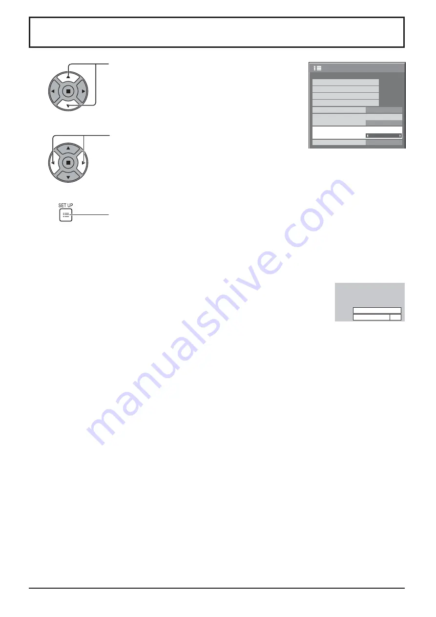
No activity power off

When this function is set to “Enable”, the power is turned off (standby) automatically when there is no operation of 

the Display for 4 hours.

Starting from 3 minutes before the turn off, the remaining time will be displayed. 

No activity power off  3min

Press any key to abort.

When the power is turned off due to this function, a message “Last turn off due to ’No activity power off’.” is 

displayed next time the power is turned on.

Note:

During the screensaver is running, this function is disabled.

1/2

Signal

Input label

ECO Mode settings

Setup

Screensaver

Wobbling

Off

OSD Language

English(UK)

Component/RGB-in select

RGB

No activity power off

Disable

Press to select the menu to adjust.

Press to select “Enable” or “Disable”.

Press to exit from Setup.

1

2

3

Summary of Contents for TH-42LF30ER

Page 1: ...h TH 42LF30ER TH 47LF30ER Operating Instructions FULL HD LCD Display Model No English Please read these instructions before operating your set and retain them for future reference ...

Page 2: ...will disappear after a while Table of Contents Important Safety Notice 3 Safety Precautions 4 Accessories 7 Accessories Supply 7 Remote Control Batteries 7 Connections 8 AC cord connection and xing 8 Video equipment connection 8 VIDEO COMPONENT RGB IN and HDMI connection 9 DVI D IN DVI D OUT connection 10 PC Input Terminals connection 11 SERIAL Terminals connection 12 Power On Off 14 Selecting the...

Page 3: ...noise to appear To avoid the possibility of harm to this appliance keep it away from sources of strong electromagnetic elds IMPORTANT THE MOULDED PLUG IMPORTANT THE MOULDED PLUG FOR YOUR SAFETY PLEASE READ THE FOLLOWING TEXT CAREFULLY This display is supplied with a moulded three pin mains plug for your safety and convenience A 10 amp fuse is tted in this plug Shall the fuse need to be replaced pl...

Page 4: ...rd may cause damage to the internal circuitry Ventilation should not be impeded by covering the ventilation openings with items such as newspapers table cloths and curtains For suf cient ventilation Leave a space of 10 cm or more at the top left and right and 5 cm or more at the rear and also keep the space between the bottom of the display and the Àoor surface Cautions for Wall Installation Wall ...

Page 5: ...electric shocks Do not do anything that may damage the power cable When disconnecting the power cable pull on the plug body not the cable Do not damage the cable make any modi cations to it place heavy objects on top of it heat it place it near any hot objects twist it bend it excessively or pull it To do so may cause re and electric shock If the power cable is damaged have it repaired at your loc...

Page 6: ...cloth or a soft lint free cloth If the surface is particularly dirty wipe with a soft lint free cloth which has been soaked in pure water or water in which neutral detergent has been diluted 100 times and then wipe it evenly with a dry cloth of the same type until the surface is dry Do not scratch or hit the surface of the panel with ngernails or other hard objects otherwise the surface may become...

Page 7: ...llation can cause battery leakage and corrosion that will damage the remote control transmitter Disposal of batteries should be in an environment friendly manner Observe the following precaution 1 Batteries shall always be replaced as a pair Always use new batteries when replacing the old set 2 Do not combine a used battery with a new one 3 Do not mix battery types example Zinc Carbon with Alkalin...

Page 8: ...UDIO IN COMPOSITE Connect the audio output of a device connected to VIDEO see page 9 COMPONENT RGB IN Component RGB Video Input Terminal see page 9 DVI D IN DVI D OUT DVI D Input Output Terminal see page 10 SERIAL IN SERIAL OUT SERIAL Input Output Terminal Control the Display by connecting to PC see page 12 AUDIO IN COMPONENT RGB Connect the audio output of a device connected to COMPONENT RGB IN s...

Page 9: ...r VIDEO COMPONENT RGB IN and HDMI connection Note Additional equipment cables and adapter plugs shown are not supplied with this set Pin No Signal Name Pin No Signal Name 1 T M D S Data2 11 T M D S Clock Shield 2 T M D S Data2 Shield 12 T M D S Clock 3 T M D S Data2 13 CEC 4 T M D S Data1 14 Reserved N C on device 5 T M D S Data1 Shield 6 T M D S Data1 15 SCL 7 T M D S Data0 16 SDA 8 T M D S Data0...

Page 10: ...standard Image deterioration may occur depending on the length or the quality of the cable DVI D Input Output Connector Pin Layouts Connection port view 9 8 1 17 24 16 Connections DVI video cable with Ferrite core Within 5 m Stereo mini plug M3 PC with DVI D video out Shared with PC IN Notes Up to 10 displays can be connected with a daisy chain but the number of the connected displays may be limit...

Page 11: ...ers with DOS V compatible Mini D sub 15P terminal The computer shown in the illustration is for example purposes only Additional equipment and cables shown are not supplied with this set Panasonic recommends using a PC cable that includes a Ferrite core Do not set the horizontal and vertical scanning frequencies for PC signals which are above or below the speci ed frequency range PC Input Terminal...

Page 12: ...a computer application such as programming language software Refer to the documentation for the computer application for details The SERIAL terminal is used when the Display is controlled by a computer Pin layout for SERIAL Terminal Communication parameters Signal level RS 232C compliant Synchronization method Asynchronous Baud rate 9600 bps Parity None Character length 8 bits Stop bit 1 bit Flow ...

Page 13: ... this unit before sending the next command If an incorrect command is sent by mistake this unit will send an ER401 command back to the computer Consult anAuthorized Service Center for detail instructions on command usage Command Command Parameter Control details PON None Power ON POF None Power OFF AVL Volume 000 100 AMT 0 Audio MUTE OFF 1 Audio MUTE ON IMS None SL1 AV1 AV2 HM1 HM2 DV1 PC1 Input s...

Page 14: ... on or in standby mode Note During operation of the power management function the power indicator turns orange in the power off state Connecting the plug to the Wall Outlet Notes Main plug types vary between countries The power plug shown at right may therefore not be the type tted to your set When disconnecting the AC cord be absolutely sure to disconnect the AC cord plug at the socket outlet rst...

Page 15: ...he power is turned ON see page 31 This message display can be set with the following menu Options menu Power On Message see page 44 15 Power On Off When rst switching on the unit Following screen will be displayed when the unit is turned on for the rst time Select the items with the remote control Unit buttons are invalid OSD Language PRESENT TIME Setup 1 Select the language 2 Set 1 Select DAY or ...

Page 16: ...HDMI1 HDMI input terminal in AV IN HDMI1 HDMI2 HDMI input terminal in AV IN HDMI2 VIDEO Video input terminal in VIDEO Component Component or RGB input terminal in COMPONENT RGB IN PC PC input terminal in PC IN DVI DVI input terminal in DVI D IN Component may be displayed as RGB depending on the setting of Component RGB in select see page 37 When an optional Terminal Board is installed PC VIDEO HDM...

Page 17: ...ng as the power cord is still inserted into the wall outlet Standby Red Orange When Slot power is set to On See page 43 Orange Depending on the type of the function board installed when the power is supplied to the slot Power ON Green PC Power management DPMS Orange With PC input signal See page 32 DVI D Power management Orange With DVI input signal See page 32 Enter Aspect button see page 19 21 I...

Page 18: ...ECO MODE setup status see page 32 FUNCTION buttons FUNCTION see page 44 Digital Zoom see page 20 AUTO SETUP button Automatically adjusts the position size of the screen see page 22 SET UP button see page 21 SOUND button see page 26 Volume Adjustment Press the Volume Up or Down button to increase or decrease the sound volume level R button see page 21 Press the R button to return to previous menu s...

Page 19: ...reen The pictures with a 4 3 aspect ratio among the 16 9 aspect ratio signals are displayed with their original aspect ratio The left and right edges of the pictures are masked with side panels Zoom1 Letterbox pictures with a 16 9 aspect ratio are enlarged vertically and horizontally so that their display lls the screen The top and bottom edges of the pictures are cut off Zoom2 Letterbox pictures ...

Page 20: ... the magni cation factor changes This is shown in the image being displayed Return to normal display quit Digital Zoom Press to exit from the Digital Zoom The cursor will move Notes When power goes OFF including Off Timer operation Digital Zoom terminates The Digital Zoom function cannot be selected while in the following operation state When MULTI DISPLAY Setup is On see page 35 When Screensaver ...

Page 21: ... on signal input and menu setting Picture menu Setup menu Pos Size menu Sound menu 100 70 50 50 50 Picture Normal Normalise Normal Brightness Picture Mode Colour Contrast Backlight Tint Advanced settings White balance Normal Sharpness 50 See page 24 25 1 2 Signal Input label ECO Mode settings Setup Screensaver Wobbling Off OSD Language English UK Component RGB in select RGB No activity power off D...

Page 22: ... the remote control is pressed Auto Setup will be executed When Auto Setup does not work Invalid is displayed Notes Auto Setup may not work when a cropped or dark image is input In such case switch to a bright image with borders and other objects are clearly shown and then try auto setup again Depending on the signal out of alignment may occur after Auto Setup Carry out ne tuning for the position ...

Page 23: ...VI HDMI On Off Notes Off is effective during only 16 9 aspect mode When Off is set H Size and V Size cannot be adjusted 1 1 Pixel Mode Adjusts the display size when 1125i or 1125p signal is input Notes On is effective during only 16 9 aspect mode Select On when you would like to replay 1920 1080 input signal Applicable input signal 1125 1080 50i 60i 24sF 24p 25p 30p 50p 60p Select Off when Àickeri...

Page 24: ...d like to change the picture and colour of the selected Picture menu to something else adjust using the items in the Picture menu see next page 1 2 Press to display the Picture menu Press to select the menu to adjust Select the desired level by looking at the picture behind the menu Select to adjust each item Press or button to switch between modes While the Picture menu is displayed if either the...

Page 25: ...More Adjusts colour saturation Tint Reddish Greenish Adjusts for nice skin colour Sharpness Less More Adjusts picture sharpness Notes Carry out W B adjustment as follows 1 Adjust the white balance of the bright sections using the W B High R W B High G and W B High B settings 2 Adjust the white balance of the dark sections using the W B Low R W B Low G and W B Low B settings 3 Repeat steps 1 and 2 ...

Page 26: ...w pitch sounds Treble Adjusts high pitch sounds Balance Adjusts left and right volumes Surround Select On or Off 3 Press to exit from adjust mode SDI Sound Output This menu is available only when selecting a slot that the following terminal board is installed HD SDI Terminal Board with audio TY FB10HD 2 2 Sound Out Right Channel Channel 1 Left Channel Channel 1 Off Level Meter Off SDI Sound Output...

Page 27: ...RESENT TIME Setup screen 1 2 PRESENT TIME Setup 1 2 Press to select DAY or PRESENT TIME Press to setup DAY or PRESENT TIME button Forward button Back Notes Pressing or button once changes PRESENT TIME 1 minute Pressing or button continuously changes PRESENT TIME by 15 minutes Press to select Set Press to store PRESENT TIME Setup Notes Set cannot be selected unless PRESENT TIME is set Unless settin...

Page 28: ... Input VIDEO 1 Set the program number 2 To execute the program set to On The program is disabled when Off is set 3 Set the day The program is executed every day when Everyday is set 4 Set the power On Off 5 Set the time Pressing or button once changes Time 1 minute Pressing or button continuously changes Time by 15 minutes 6 Set the input Notes This function cannot be set unless PRESENT TIME Setup...

Page 29: ...select Screensaver Press to display Screensaver screen Mode selection Start setting 4 When the Mode is set to On press to select Start Press to start Screensaver The menu screen will disappear and the Screensaver will be activated To stop the Screensaver under On press the R button or any buttons on the main unit Note When the display is turned off the Scrensaver will be deactivated Press to selec...

Page 30: ...ff OSD Language English UK Component RGB in select RGB No activity power off Disable 30 After selecting Time Designation Interval or Standby after SCR Saver the relevant Time Setup will become available for selection and the Operating Time may be set Time cannot be set when Mode is On or Off Press to select Start Time Finish Time When Time Designation is selected Press to select Periodic Time Oper...

Page 31: ...key to abort When the power is turned off due to this function a message Last turn off due to No activity power off is displayed next time the power is turned on Note During the screensaver is running this function is disabled 1 2 Signal Input label ECO Mode settings Setup Screensaver Wobbling Off OSD Language English UK Component RGB in select RGB No activity power off Disable Press to select the...

Page 32: ...l input ĺ Power is turned off standby the power indicator lights up orange When pictures are subsequently detected ĺ Power is turned on the power indicator lights up green Notes This function operates only during input from PC IN terminal This function is effective when Sync is set to Auto and during normal viewing one picture screen DVI D Power management When this function is set to On it operat...

Page 33: ...input Input label SLOT INPUT 1 SLOT INPUT DVD1 DVD2 DVD3 Blu ray1 Blu ray2 Blu ray3 CATV VCR STB Skip VIDEO VIDEO DVD1 DVD2 DVD3 Blu ray1 Blu ray2 Blu ray3 CATV VCR STB Skip Component 2 Component DVD1 DVD2 DVD3 Blu ray1 Blu ray2 Blu ray3 CATV VCR STB Skip PC PC DVD1 DVD2 DVD3 Blu ray1 Blu ray2 Blu ray3 CATV VCR STB Skip DVI DVI DVD1 DVD2 DVD3 Blu ray1 Blu ray2 Blu ray3 CATV VCR STB Skip HDMI1 HDMI...

Page 34: ...nglish UK Deutsch Français Italiano Español English US Chinese Japanese Ɋɭɫɫɤɢɣ Russian Press to display the Setup menu Press to select Menu Display Duration Press to adjust the display duration Press to select Menu Transparency Press to adjust the transparency Press to exit from adjust mode 1 4 2 3 Customizing the On Screen Menu Display 2 2 Setup MULTI DISPLAY Setup Set up TIMER PRESENT TIME Setu...

Page 35: ...isplays in groups for example as illustrated below an enlarged picture may be displayed across all screens For this mode of operation each display has to be set up with a Display number to determine its location Example group of 16 4 4 group of 4 2 2 group of 9 3 3 group of 25 5 5 Item Details MULTI DISPLAY Setup Select On or Off Horizontal Scale Select 1 2 3 4 5 Vertical Scale Select 1 2 3 4 5 Be...

Page 36: ...one of for the units digit setting 4 Notes The numbers in 2 3 and 4 should be set up quickly Adjustable ID number range is 0 99 If a number button is pressed more than two times the rst two numbers become the ID number for the remote control ID Cancellation Press button on remote control This has the same effect as pressing the buttons at the same time Notes Set the Remote ID On to operate the ID ...

Page 37: ...rce connected to the COMPONENT RGB IN terminal Y PB PR signals Component RGB signals RGB 1 2 Press to display the Setup menu Press to select the Component RGB in select Press to select the desired input signal Component RGB Press to exit from adjust mode Note Make setting of the selected input terminal COMPONENT RGB IN 3 YUV RGB in select Select to match the signals from the source connected to DV...

Page 38: ... XGA Mode 1024 768 Cinema reality Off Sync Signal H Freq V Freq kHz Hz 63 98 60 02 Signal Format 1280 1024 60 RGB Cinema reality Noise reduction XGA Mode Auto Off Off 1024 768 38 3D Y C Filter Select Signal from the Setup menu during Video input signal Signal AV menu is displayed Press to select the 3D Y C Filter Press to set On Off Setup for Input Signals Signal menu Press ACTION button For Video...

Page 39: ...e When On this setting only affects the following signal input NTSC PAL signal input during Video input signal 525i 480i 625i 575i 1125 1080 60i signal input during Component input signal Colour system Set the colour system to match the input signal When Auto is set Colour system will be automatically selected from NTSC PAL SECAM NTSC 4 43 PAL M PAL N To display PAL60 signal select Auto y XGA Mode...

Page 40: ...d If both input it is selected the H and V sync However the synchronized signal that is input rst is selected on G Uses a synchronized signal on the Video G signal which is input from the G connector Note Accepts only RGB signals from COMPONENT RGB IN terminal with Sync on G Sync Press to select the Sync Press to adjust Switches the dynamic range according to the input signal from HDMI terminal Vi...

Page 41: ...lays the frequency and the type of the current input signal This display is valid only for Component RGB PC and Digital input signal Display range Horizontal 30 110 kHz Vertical 48 120 Hz The dot clock frequency is displayed during digital signal input Note The automatically detected signal format may be displayed differently than the actual input signal Input signal display ...

Page 42: ...d when an optional Terminal Board is installed Notes When other than Off is set Input lock will be grayed out and cannot be set When Input lock is set to other than Off this setting will be grayed out and cannot be set Initial VOL level Press button to adjust the volume when the unit is turned on Off On Off Sets normal volume On Sets your preferred volume Notes When Maximum VOL level is On the vol...

Page 43: ...red orange On Power returns in power On Power Indicator green Note When using multiple displays Standby is preferred to be set in order to reduce a power load ID select Sets panel ID number when panel is used in Remote ID or Serial ID Set value range 0 100 Standard value 0 Remote ID The setting of this menu is valid only when using ID remote control Off Disables ID remote control functions You can...

Page 44: ...wer off Precautions at the time of power ON is set On The warning precautions are shown at the time of power ON Off The warning precautions are not shown at the time of power ON Note This setting is enabled only if No activity power off is Enable see page 31 Function button assign 1 Function button assign 2 Set the functions that operates when is pressed Signal The Signal menu is displayed Screens...

Page 45: ... being driven may be heard This is normal and not indicative of malfunctioning Parts of the unit become hot Even when the temperature of parts of the front top and rear panels has risen these temperature rises will not pose any problems in terms of performance or quality Power automatically turns off unexpectedly Check the settings of No signal power off PC Power management DVI D Power management ...

Page 46: ...900 65Hz 61 20 65 20 92 0 92 0 92 0 31 1 152x900 66Hz 61 85 66 00 94 5 94 5 94 5 32 1 152x900 75Hz 71 40 75 60 105 1 105 1 105 1 33 1 280x768 60Hz 47 78 59 87 79 50 79 50 79 50 34 1 280x800 50Hz 41 20 50 00 68 55 68 55 68 55 35 1 280x960 60Hz 60 00 60 00 108 0 108 0 108 0 36 1 280x960 85Hz 85 94 85 00 148 5 148 5 148 5 37 1 280x1 024 50Hz 52 70 50 00 89 38 89 38 89 38 38 1 280x1 024 60Hz 63 34 59 ...

Page 47: ...47 59 94 27 0 27 0 3 625 575 50i 15 63 50 00 13 5 4 625 576 50i 15 63 50 00 27 0 5 625 575 50p 31 25 50 00 27 0 6 625 576 50p 31 25 50 00 27 0 7 750 720 60p 45 00 60 00 74 25 74 25 8 750 720 50p 37 50 50 00 74 25 74 25 9 1 125 1 080 60p 67 50 60 00 148 5 1 148 5 10 1 125 1 080 60i 33 75 60 00 74 25 1 74 25 11 1 125 1 080 50p 56 25 50 00 148 5 1 148 5 12 1 125 1 080 50i 28 13 50 00 74 25 1 74 25 13...

Page 48: ...itch on main unit to turn the power off This function allows you to reset the unit to the factory setting Shipping condition 1 2 3 4 Press to display the Setup menu Press to select OSD Language Press for more than 3 seconds Wait for 10 seconds 5 6 Press the power switch on main unit to turn the power off Press to select Shipping Press to display the Shipping menu Press to select YES Press to con r...

Page 49: ...20 60p 50p 1125 1080 60i 60p 50i 50p 24p 25p 30p 24sF PC signals VGA SVGA XGA SXGA UXGA compressed Horizontal scanning frequency 30 110 kHz Vertical scanning frequency 48 120 Hz Connection terminals VIDEO AUDIO L R BNC RCA Pin jack 2 1 0 Vp p 75 ȍ 0 5 Vrms HDMI 1 2 TYPE A Connector COMPONENT RGB IN G Y B PB CB R PR CR AUDIO L R BNC BNC BNC RCA Pin jack 2 with sync 1 0 Vp p 75 ȍ 0 7 Vp p 75 ȍ 0 7 V...

Page 50: ...ay be applicable for incorrect disposal of this waste in accordance with national legislation For business users in the European Union If you wish to discard electrical and electronic equipment please contact your dealer or supplier for further information Information on Disposal in other Countries outside the European Union These symbols are only valid in the European Union If you wish to discard...

Reviews: