background image

25

PICTURE Adjustments

ADVANCED SETTINGS

Notes:

•  “COLOR” and “TINT” settings cannot be 

adjusted for “RGB/PC” and “Digital” input 
signal.

•  You can change the level of each function 

(PICTURE, BRIGHTNESS, COLOR, TINT, 
SHARPNESS) for each PICTURE MENU.

• The “TINT” setting can be adjusted 

for NTSC signal only during “VIDEO 
(S VIDEO)” input signal.

• In PICTURE, there is not a noticeable 

change even when contrast is increased 
with a bright picture or reduced with a dark 
picture.

On the remote control unit, while the “ADVANCED SETTINGS” menu is displayed, if either the N button is pressed at 
any time or the ACTION (  ) button is pressed during “NORMALIZE”, then all adjustment values are returned to the 
factory settings.

Helpful Hint (    / 

NORMALIZE

  Normalization)

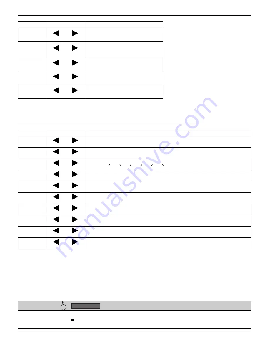
Item

Effect Adjustments

PICTURE

Less

More

Adjusts the proper picture contrast.

BRIGHTNESS

Darker

Brighter

Adjusts for easier viewing of dark 
pictures such as night scenes and 
black hair.

COLOR

Less

More

Adjusts color saturation.

TINT

Reddish

Greenish

Adjusts for natural fl esh tones.

SHARPNESS

Less

More

Adjusts picture sharpness.

Item

Effect Details

BLACK

EXTENSION

Less

More

Adjusts the dark shades of the image in gradation.

INPUT 

LEVEL

Less

More

Adjustment of parts which are extremely bright and hard to see.
(This cannot be adjusted when the input signal is Digital.)

GAMMA

Down

Up

S CURVE 

  2.0 

  2.2 

   2.5

AGC

OFF

ON

Increases the brightness of dark signal automatically.

W/B HIGH R

Less

More

Adjusts the white balance for light red areas.

W/B HIGH G

Less

More

Adjusts the white balance for light green areas.

W/B HIGH B

Less

More

Adjusts the white balance for light blue areas.

W/B LOW R

Less

More

Adjusts the white balance for dark red areas.

W/B LOW G

Less

More

Adjusts the white balance for dark green areas.

W/B LOW B

Less

More

Adjusts the white balance for dark blue areas.

Notes:

•  Carry out “W/B” adjustment as follows.

1.

 Adjust the white balance of the bright sections using the “W/B HIGH R” , “W/B HIGH G” and “W/B HIGH B” settings.

2.

 Adjust the white balance of the dark sections using the “W/B LOW R” , “W/B LOW G” and “W/B LOW B” settings.

3.

 Repeat steps 

1

 and 

2

 to adjust.

 Steps 

1

 and 

2

 affect each other’s settings, so repeat each step in turn to make the adjustment.

•  The adjustment values are memorized separately for each input terminal.
•  The adjustment range values should be used as an adjustment reference.

Summary of Contents for TH-103PF10UK - 103" Plasma Panel

Page 1: ...s an image Before connecting operating or adjusting this product please read these instructions completely Please keep this manual for future reference English Model No Operating Instructions High Definition Plasma Display TH 103PF10UK ...

Page 2: ...DO NOT OPEN WARNING To prevent damage which may result in fire or shock hazard do not expose this apparatus to rain or moisture Do not place containers with water flower vase cups cosmetics etc above the set including on shelves above etc WARNING 1 To prevent electric shock do not remove cover No user serviceable parts inside Refer servicing to qualified service personnel 2 Do not remove the groun...

Page 3: ...ent of the obsolete outlet 10 Protect the power cord from being walked on or pinched particularly at plugs convenience receptacles and the point where they exit from the apparatus 11 Only use attachments accessories specified by the manufacturer 12 Use only with the cart stand tripod bracket or table specified by the manufacturer or sold with the apparatus When a cart is used use caution when movi...

Page 4: ...ge 18 ASPECT Controls 19 Adjusting POS SIZE 20 MULTI PIP 22 Advanced PIP 23 PICTURE Adjustments 24 ADVANCED SETTINGS 25 SOUND Adjustment 26 SDI Sound Output 27 SURROUND 27 MUTE 27 Digital Zoom 28 PRESENT TIME SETUP SET UP TIMER 29 PRESENT TIME SETUP 29 SET UP TIMER 30 SCREENSAVER For preventing image retention 31 Setup of SCREENSAVER Time 32 Reduces screen image retention 32 SIDE BAR ADJUST 33 Red...

Page 5: ... interference that may cause undesired operation FCC CAUTION To assure continued compliance use only shielded interface cables when connecting to computer or peripheral devices Any changes or modifications not expressly approved by Panasonic Corporation of North America could cause harmful interference and would void the user s authority to operate this device FCC Declaration of Conformity Model N...

Page 6: ... cloth This Plasma Display radiates infrared rays therefore it may affect other infrared communication equipment Install your infrared sensor in a place away from direct or reflected light from your Plasma Display Note Do not allow a still picture to be displayed for an extended period as this can cause a permanent image retention to remain on the Plasma Display Examples of still pictures include ...

Page 7: ... can cause fire or damage to the Plasma Display Transport only in upright position Transporting the unit with its display panel facing upright or downward may cause damage to the internal circuitry If using the Plasma Display leave a space of at least 12 0 30 cm at the top left and right at least 6 0 15 cm at the bottom and at least 8 0 20 cm at the rear AC Power Supply Cord The Plasma Display is ...

Page 8: ...ypes example Zinc Carbon with Alkaline 4 Do not attempt to charge short circuit disassemble heat or burn used batteries 5 Battery replacement is necessary when the remote control acts sporadically or stops operating the Plasma Display 3 Replace the cover Accessories Supplied Check that you have the Accessories and items shown Remote Control Batteries AA size Helpful Hint For frequent remote contro...

Page 9: ...fixing bands Secure any excess cables with bands as required Pass the attached cable fixing band through the clip as shown in the figure To secure cables connected to Terminals wrap the cable fixing band around them then pass the pointed end through the locking block as shown in the figure While ensuring there is sufficient slack in cables to minimize stress especially in the power cord firmly bin...

Page 10: ... There is no need to use an adapter for computers with DOS V compatible Mini D sub 15P terminal The computer shown in the illustration is for example purposes only Additional equipment and cables shown are not supplied with this set Do not set the horizontal and vertical scanning frequencies for PC signals which are above or below the specified frequency range Component Input is possible with the ...

Page 11: ...for the response for the first command to come from this unit before sending the next command If an incorrect command is sent by mistake this unit will send an ER401 command back to the computer SL1A SL1B SL2A and SL2B of Command IMS are available only when a dual input terminal board is attached 6 7 8 9 1 3 4 5 2 SERIAL Pin layout for SERIAL Terminal COMPUTER RS 232C Straight cable D sub 9p Start...

Page 12: ...NT RGB IN HDMI AV OUT HDMI AV OUT HDMI connection This unit has terminal boards equivalent to Dual HDMI Terminal Board TY FB10HMD and BNC Component Video Terminal Board TY 42TM6A as standard equipment HDMI cables DVD player DVD player Pin assignments and signal names 19 3 1 4 2 18 Note Additional equipment and HDMI cables shown are not supplied with this set Pin No Signal Pin No Signal 1 T M D S D...

Page 13: ...yed From the second time on language selection can be done from the setup menu see page 18 Select the desired language using the or button and press the ACTION button Note Set with the remote control Buttons on the main unit are unavailable for this setting From the second time on the screen shown below is displayed for a while setting condition is an example English UK Deutsch Français Italiano E...

Page 14: ...ICTURE SETUP SOUND POS SIZE Main Power On Off Switch Enter Aspect button see page 16 19 INPUT button INPUT1 INPUT2 INPUT3 and PC selection see page 18 Right side surface Power Indicator The Power Indicator will light Power OFF Indicator not illuminated The unit will still consume some power as long as the power cord is still inserted into the wall outlet Standby Red Power ON Green DPMS Orange With...

Page 15: ... minutes remain OFF TIMER 3 will flash The off timer is cancelled if a power interruption occurs Status button Press the Status button to display the current system status 1 Input label 2 Aspect mode see page 19 3 Off timer The off timer indicator is displayed only when the off timer has been set R button see page 17 Press the R button to return to previous menu screen POSITION buttons ACTION butt...

Page 16: ...L OFF ON PICTURE 1 Press to select 2 Press to access each adjust screen To POS SIZE adjust menu see page 20 To SOUND adjust menu see page 26 0 0 0 1 2 SOUND NORMAL NORMALIZE OFF TREBLE BALANCE BASS 0 MID SURROUND MAIN AUDIO OUT PIP 0 NORMAL NORMALIZE AUTO SETUP POS SIZE V POS 0 H POS V SIZE DOT CLOCK H SIZE CLOCK PHASE 1 1 PIXEL MODE OFF 0 0 0 0 During VIDEO S VIDEO Digital SDI and HDMI input sign...

Page 17: ...ION OFF OFF PRESENT TIME OF DAY 99 99 Press the R button to return to SET UP menu Press to select START TIME FINISH TIME When TIME OF DAY is selected Press to select SHOW DURATION SAVER DURATION When INTERVAL is selected Press to set up To setup SCREENSAVER see page 31 33 To setup MULTIDISPLAY screen see page 35 INTERVAL SCREENSAVER START FUNCTION MODE WOBBLING PEAK LIMIT WHITE BAR SCROLL 6 15 12 ...

Page 18: ...stalled into the SLOT Select to match the signals from the source connected to the component RGB input terminals see page 40 In 2 screen display the same input mode cannot be selected for the main picture and sub picture Image retention image lag may occur on the plasma display panel when a still picture is kept on the panel for an extended period The function that darkens the screen slightly is a...

Page 19: ...ecome enlarged depending on the picture source allowing you to view the picture at its maximum size Notes Panasonic AUTO mode is designed to automatically adjust the aspect ratio to handle a mix of 16 9 and 4 3 program material Certain 4 3 program material such as stock market data screens may occasionally cause the image size to change unexpectedly When viewing such programs it is recommended tha...

Page 20: ... 525 480 60i 60p 625 575 50i 50p 1125 1080 60i 50i 60p 50p 24p 25p 30p 24sF 1250 1080 50i 750 720 60p 50p each and RGB PC Digital signals are memorized for each frequency If a Cue or Rew signal from a VCR or DVD player is received the picture position will shift up or down This picture position movement cannot be controlled by the POS SIZE function If adjusting the PICTURE V POS V SIZE in Panasoni...

Page 21: ...t be adjusted automatically Select NORMALIZE in POS SIZE and press the ACTION button when appropriate adjustment cannot be made H POS Adjust the horizontal position H SIZE Adjust the horizontal size V POS Adjust the vertical position V SIZE Adjust the vertical size DOT CLOCK During COMPONENT RGB and PC input signal Periodic striped pattern interference noise may occur when a striped pattern is dis...

Page 22: ...PUT lock in Options menu is set to other than Off MULTI PIP function isn t available Sound output is from the picture which is selected in Audio OUT PIP see page 26 In 2 screen display the same input mode cannot be selected for the main picture and sub picture The main picture and sub picture are processed by different circuits resulting in a slight difference in the clarity of the pictures There ...

Page 23: ...be possible to discern details on them satisfactorily Following combinations of two analog signals cannot be displayed simultaneously Component Component Component PC RGB PC RGB Component PC RGB PC RGB Refer to each board s operating instruction for DVI SDI HDMI s corresponding signals Press repeatedly Each time pressing this button main picture and sub picture will be displayed as above Note To u...

Page 24: ...vel see next page ADVANCED SETTINGS OFF Displays images with settings of the PICTURE menu Press to enter Advanced Settings COLOR MANAGEMENT ON Enables vivid color adjustment automatically While the PICTURE menu is displayed if either the N button on the remote control is pressed at any time or the ACTION button is pressed during NORMALIZE then all adjustment values are returned to the factory sett...

Page 25: ...ffect Details BLACK EXTENSION Less More Adjusts the dark shades of the image in gradation INPUT LEVEL Less More Adjustment of parts which are extremely bright and hard to see This cannot be adjusted when the input signal is Digital GAMMA Down Up S CURVE 2 0 2 2 2 5 AGC OFF ON Increases the brightness of dark signal automatically W B HIGH R Less More Adjusts the white balance for light red areas W ...

Page 26: ...s to select the menu to adjust Select the desired level by listening to the sound 2 Select to adjust each item While the SOUND menu is displayed if either the N button on the remote control is pressed at any time or the ACTION button is pressed during NORMALIZE then all adjustment values are returned to the factory settings Helpful Hint NORMALIZE Normalization Musical note is displayed on right si...

Page 27: ... Meter OFF SDI Sound Output Item Details Left Channel Channel 1 to Channel 16 Selects left audio channel Right Channel Channel 1 to Channel 16 Selects right audio channel Sound Out ON OFF ON Enables audio output OFF Disables audio output Level Meter OFF 1 8ch 9 16ch Sets audio channels to show in the audio level meter 8 channels are displayed in the audio level meter 4 channels each on both right ...

Page 28: ...MULTI DISPLAY SETUP is ON see page 35 When PORTRAIT SETUP is ON see page 38 When SCREENSAVER WHITE BAR SCROLL is running see page 31 While Digital Zoom is in operation Adjusting POS SIZE cannot be used Select the magnification required for the enlarged display Each time this is pressed the magnification factor changes This is shown in the image being displayed 3 2 4 The cursor will move 2 EXIT 2 1...

Page 29: ...REENSAVER MULTI DISPLAY SETUP 99 99 MON PRESENT TIME SETUP PRESENT TIME OF DAY MON 99 99 SET PRESENT TIME OF DAY DAY 10 00 TUE PRESENT TIME SETUP PRESENT TIME OF DAY MON 99 99 SET PRESENT TIME OF DAY DAY Display the PRESENT TIME SETUP screen To set up DAY and PRESENT TIME OF DAY follow the procedure described below Press to select DAY or PRESENT TIME OF DAY Press to set up DAY or PRESENT TIME OF D...

Page 30: ... TIME POWER OFF TIME by 15 minutes Press to select POWER ON FUNCTION POWER OFF FUNCTION Press to select ON Press twice to exit from SET UP Note Timer function will not work unless PRESENT TIME OF DAY is set Display the SET UP TIMER SCREEN 1 2 3 0 00 0 00 SET UP TIMER POWER OFF FUNCTION POWER OFF TIME POWER ON TIME POWER ON FUNCTION OFF OFF PRESENT TIME OF DAY 99 99 0 00 0 00 SET UP TIMER POWER OFF...

Page 31: ...turned off the SCREENSAVER will be deactivated Press to select the MODE Press to select each mode items OFF INTERVAL Operates when SHOW DURATION and SAVER DURATION are set up and those times arrive TIME OF DAY Operates when START TIME and FINISH TIME are set up and those times arrive ON Operates when START is selected and the ACTION button is pressed SCREENSAVER For preventing image retention 2 2 ...

Page 32: ...2 3 1 Press to display the SET UP menu SCREENSAVER For preventing image retention SCREENSAVER START FUNCTION MODE WOBBLING PEAK LIMIT FINISH TIME START TIME WHITE BAR SCROLL OFF 6 15 12 30 OFF OFF SIDE BAR ADJUST BRIGHT PRESENT TIME OF DAY 99 99 SCREENSAVER START FUNCTION MODE WOBBLING PEAK LIMIT WHITE BAR SCROLL 6 15 12 30 OFF OFF INTERVAL SIDE BAR ADJUST BRIGHT SAVER DURATION SHOW DURATION PRESE...

Page 33: ...tion guide steps 1 and 2 Notes To reduce the occurrence of image retention set the SIDE BAR ADJUST to BRIGHT The side bar may flash alternate black white depending on the picture being shown on the screen Using Cinema mode will reduce such flashing side bars NORMAL mode image retention Picture out Picture Picture and Picture Non picture area This function may be applicable to the non picture area ...

Page 34: ...the label of the Input signal to be displayed Select the input signal which you would like to change its label before customizing the Input labels see page 15 18 Note While selecting a Input signal through Optional Terminal Board connected to Slot 1 Slot 2 and Slot 3 the Input label will depend on each Optional Terminal Board INPUT LABELS for Slot 1 Slot 2 Slot 3 and Mini D sub Slot1 Input INPUT1 ...

Page 35: ...LAY SETUP menu Press to select the MULTI DISPLAY SETUP Press to select ON or OFF How to setup MULTI DISPLAY group of 16 4 4 group of 4 2 2 group of 9 3 3 1 2 3 2 2 SET UP SCREENSAVER MULTI DISPLAY SETUP SET UP TIMER PORTRAIT SETUP PRESENT TIME SETUP 2 MULTI DISPLAY SETUP HORIZONTAL SCALE OFF A1 OFF AI SYNCHRONIZATION VERTICAL SCALE LOCATION OFF SEAM HIDES VIDEO 2 MULTI DISPLAY SETUP SET UP for MUL...

Page 36: ... E5 4 4 Press to select HORIZONTAL SCALE Press to select 1 2 3 4 5 Press to select LOCATION Press to select the required arrangement number A1 E5 Refer to the following A1 OFF AI SYNCHRONIZATION LOCATION 2 MULTI DISPLAY SETUP HORIZONTAL SCALE OFF OFF VERTICAL SCALE SEAM HIDES VIDEO 2 MULTI DISPLAY SETUP 5 Press to select VERTICAL SCALE Press to select 1 2 3 4 5 6 Press to select SEAM HIDES VIDEO P...

Page 37: ...sed when ID select is set to anything other than 0 and the remote control ID is not the same as the ID select number see page 46 ID remote control button operation The operation is the same as normal remote control except for the button 8 MULTI DISPLAY SETUP ON OFF MULTI DISPLAY SETUP HORIZONTAL SCALE VERTICAL SCALE SEAM HIDES VIDEO A1 LOCATION 2 2 AI SYNCHRONIZATION OFF Press to select AI Control...

Page 38: ...splays Suitable for still image display ON OFF 2 2 SET UP SCREENSAVER MULTI DISPLAY SETUP PORTRAIT SETUP SET UP TIMER PRESENT TIME SETUP OFF PORTRAIT SETUP SEAM HIDES VIDEO OFF 1 OFF AI SYNCHRONIZATION VIEWING AREA LOCATION 16 9 PORTRAIT SETUP OFF PORTRAIT SETUP SEAM HIDES VIDEO OFF 1 OFF AI SYNCHRONIZATION VIEWING AREA LOCATION 16 9 PORTRAIT SETUP Divide an input image into 3 parts and display on...

Page 39: ...IT SETUP SEAM HIDES VIDEO OFF 1 OFF AI SYNCHRONIZATION VIEWING AREA LOCATION 16 9 PORTRAIT SETUP 5 VIEWING AREA Set a mode of image division for PORTRAIT function LOCATION Set a location of image to be displayed for PORTRAIT function VIEWING AREA LOCATION When PORTRAIT SETUP ON Display the image of the selected location When PORTRAIT SETUP is OFF Represent an area of the selected LOCATION at a nor...

Page 40: ...ed Note When ON this setting only affects NTSC input signals Note Selection may not be possible depending on which optional board is installed 1 2 1 2 PC OFF STANDBY SAVE OFF POWER MANAGEMENT OFF AUTO POWER OFF OFF OSD LANGUAGE ENGLISH US COMPONENT RGB IN SELECT RGB INPUT LABEL SIGNAL POWER SAVE SET UP 1 2 PC OFF STANDBY SAVE OFF POWER MANAGEMENT OFF AUTO POWER OFF OFF OSD LANGUAGE ENGLISH US COMP...

Page 41: ...om adjust mode VIDEO NR Automatically reduces unwanted picture noise Block NR Reduces block noise when playing MPEG videos Mosquito NR Reduces mosquito noise around subtitles on MPEG videos Note VIDEO NR cannot be adjusted while a PC signal is being applied 1 2 SET UP for Input Signals VIDEO NR Block NR Mosquito NR 1 2 PC OFF STANDBY SAVE OFF POWER MANAGEMENT OFF AUTO POWER OFF OFF OSD LANGUAGE EN...

Page 42: ...r system to match the input signal When selecting AUTO the color system is automatically selected from NTSC PAL SECAM however M NTSC signal is not displayed properly depending on the attached terminal board To display M NTSC signal select M NTSC in COLOR SYSTEM AUTO SECAM M NTSC NTSC PAL Panasonic AUTO 4 3 Set to NORMAL to view 4 3 images in an unchanged format when PanasonicAUTO is selected If yo...

Page 43: ... G signal which is input from the G connector VBS Uses a synchronized signal of Composite Sync input which is input from the HD connector Displays the H Horizontal V Vertical frequencies This display is valid only for RGB PC and Digital input signal Display range Horizontal 15 110 kHz Vertical 48 120 Hz H FREQ kHz V FREQ Hz 1 2 PC OFF STANDBY SAVE OFF POWER MANAGEMENT OFF AUTO POWER OFF OFF OSD LA...

Page 44: ...the adjusted signal is displayed see page 18 Signal can be displayed when the Terminal board is installed This menu is available only when INPUT lock is Off When a dual input terminal board is attached A or B is displayed depending on the selected input signal Ex INPUT1A INPUT1B Press to select OSD Language Press and hold until the Options menu is displayed Press to select your preferred menu Pres...

Page 45: ...ff is set the value will be fixed as the value input in the single screen display mode When a dual input terminal board is attached A or B is displayed depending on the selected input signal Ex INPUT1A INPUT1B Button lock Off MENU ENTER On Off All the buttons at the right side of the main unit can be used MENU ENTER Locks MENU MENU and ENTER ENTER buttons on right side of main unit On Locks all th...

Page 46: ...al image display size on screen On Sets the image display size approximately 95 of the normal image display Off On Notes This setting is valid only when the input signals are as follows NTSC PAL SECAM M NTSC PAL60 PAL M PAL N BNC Dual Video Terminal Board TY FB9BD 525i 525p 625i 625p 750 60p 750 50p 1125 60i 1125 50i 1125 24sF 1125 25p 1125 24p 1125 30p 1125 60p 50p 1250 50i Component Video RGB DV...

Page 47: ... is in standby mode and also the power is being supplied to a terminal board the unit will start supplying the power to the board with time delay according to the setting The power indicator lights up red first and it turns orange when the power starts being supplied to the board V Installation Off On Off Sets fan to the horizontal installation mode On Sets fan to the vertical installation mode No...

Page 48: ...OOM AVL 10 07 08 1 Program Program number Options Adjustments Weekly Command Timer You can set 7 day timer programming by setting time and command Note Before setting Weekly Command Timer set PRESENT TIME SETUP see page 29 Press to select Function Press to select On Note When Function is set to On SET UP TIMER see page 30 is unavailable and INTERVAL TIME OF DAY in MODE of SCREENSAVER see page 31 c...

Page 49: ...elect Command No Press to select a command number 6 Press to select Time Command Press to set each item Time Set the time to execute a command program Pressing or button once changes Time 1 minute Pressing or button continuously changes Time by 15 minutes Command Select a command to execute at the set time This unit has 64 commands to set see page 54 Notes Command is performed in order of executio...

Page 50: ...up menu is displayed 2 Press the Volume Up or Down button to select OSD LANGUAGE 3 Press and hold the ENTER button till the SHIPPING menu is displayed 4 Press the Volume Up or Down button to select YES 5 Press the ENTER button and wait for 10 sec Note Press the R button to return to SET UP menu when SHIPPING menu is displayed 1 2 PC OFF STANDBY SAVE OFF POWER MANAGEMENT OFF AUTO POWER OFF OFF OSD ...

Page 51: ... between image and audio depending on the type of input signal However this is not a malfunction Plasma Display panel Symptoms Check The screen darkens slightly when bright pictures with minimal movements are shown The screen will darken slightly when photos still images of a computer or other pictures with minimal movements are shown for an extended period This is done to reduce image retention o...

Page 52: ...1 15 1 125 1 080 24p 27 00 24 00 74 25 1 16 1 250 1 080 50i 31 25 50 00 74 25 2 17 640 400 70 Hz 31 46 70 07 25 17 18 640 480 60 Hz 31 47 59 94 25 18 5 19 640 480 72 Hz 37 86 72 81 31 5 20 640 480 75 Hz 37 50 75 00 31 5 21 640 480 85 Hz 43 27 85 01 36 0 22 800 600 56 Hz 35 16 56 25 36 0 23 800 600 60 Hz 37 88 60 32 40 0 24 800 600 72 Hz 48 08 72 19 50 0 25 800 600 75 Hz 46 88 75 00 49 5 26 800 600...

Page 53: ...Total number of lines 1 VGA60 59 94 31 47 25 18 640 800 480 525 2 525 60p 59 94 31 47 27 00 720 858 480 525 3 625 50p 50 00 31 25 27 00 720 864 576 625 4 750 60p 60 00 45 00 74 25 1280 1650 720 750 5 750 50p 50 00 37 50 74 25 1280 1980 720 750 6 1125 60i 60 00 33 75 74 25 1920 2200 1080 1125 7 1125 50i 50 00 28 13 74 25 1920 2640 1080 1125 8 1125 60p 60 00 67 50 148 50 1920 2200 1080 1125 9 1125 5...

Page 54: ...icture 36 DWA POP Dual Picture mode Picture out Picture 37 DWA SWP Swap main picture and sub picture when PIP mode 38 DWA TWN Dual Picture mode Picture and Picture 39 IMS PC1 Input select PC1 Main Picture when PIP mode 40 IMS SL1 Input select SLOT1 Main Picture when PIP mode 41 IMS SL1A Input select SLOT1A Main Picture when PIP mode 42 IMS SL1B Input select SLOT1B Main Picture when PIP mode 43 IMS...

Page 55: ...8 120 Hz Connection terminals HDMI A B TYPE A Connector 2 COMPONENT RGB IN Y G BNC PB B BNC PR R BNC AUDIO IN RCA PIN JACK 2 with sync 1 0 Vp p 75 Ω 0 7 Vp p 75 Ω 0 5 Vrms high impedance PC IN HIGH DENSITY MINI D SUB 15PIN B PB CB R PR CR HD VD AUDIO IN M3 JACK Y or G with sync 1 0 Vp p 75 Ω Y or G without sync 0 7 Vp p 75 Ω 0 7 Vp p 75 Ω 0 7 Vp p 75 Ω 1 0 5 0 Vp p high impedance 0 5 Vrms high imp...

Page 56: ...OR CONSEQUENTIAL DAMAGES INCLUDING WITHOUT LIMITION DAMAGE TO DISCS RESULTING FROM THE USE OF THIS PRODUCT OR ARISING OUT OF ANY BREACH OF THE WARRANTY ALL EXPRESS AND IMPLIED WARRANTIES INCLUDING THE WARRANTIES OF MERCHANTABILITY AND FITNESS FOR PARTICULAR PURPOSE ARE LIMITED TO THE APPLICABLE WARRANTY PERIOD SET FORTH ABOVE Some states do not allow the exclusion or limitation of incidental or co...

Page 57: ... coverage period Proof of product purchase is a condition of warranty service The owner must produce the product purchase receipt or other satisfactory evidence of date of original purchase This warranty does not apply to external appearance items such as handles knobs safety windows etc This warranty does not apply to any part or parts of the product installed altered repaired or misused in any w...

Page 58: ...Memo 58 ...

Page 59: ...Memo 59 ...

Page 60: ...A 90068 323 436 3500 Dallas Region 6226 Abington Way Houston TX 77008 713 802 2726 No CA Northwest Region 5870 Stone Ridge 3 Pleasanton CA 925 416 5108 Government Marketing Department 52 West Gude Drive Rockville MD 20850 301 738 3840 Panasonic Canada Inc 5770 Ambler Drive Mississauga Ontario L4W 2T3 Customer s Record The model number and serial number of this product can be found on its back cove...

Reviews: