background image

Page 4 of  13

Model
Name

Model
No.

Switch-M8eGi

PN28080i-ID

Product Specification

401-28080i-ID-SP01

Panasonic Life Solutions Networks Co., Ltd.

Date revised

Date issued

May. 26, 2020

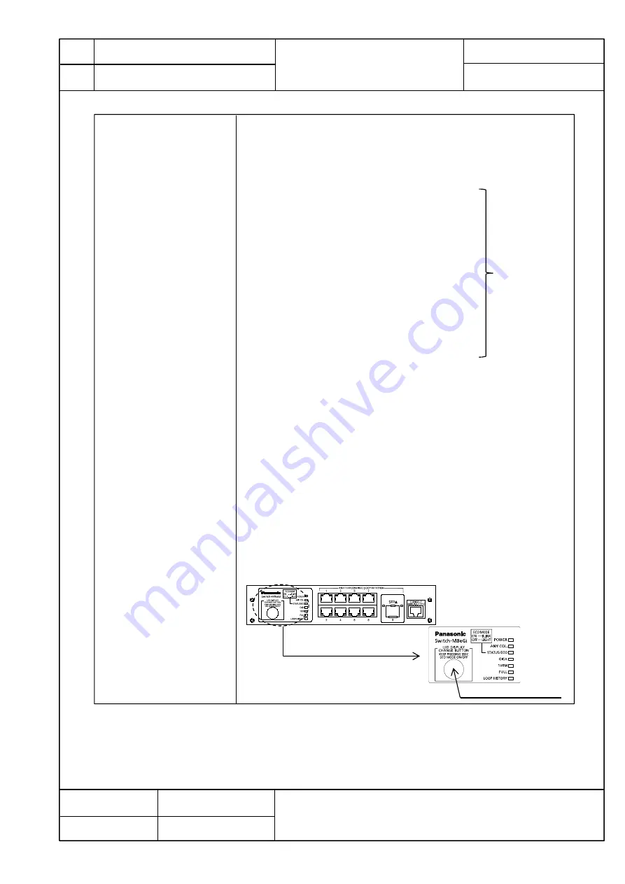
(1)POWER(Power)LED

Green Light :Power is ON
Off

:Power is OFF

(2)ANY COL.(Collision) LED

Orange Light : During half-duplex operation,  packet collision is 

occurring in either port.

(3)STATUS/ECO (Status/ECO made)LED

Green Light   : Operating in status mode.
Green Blink : Operating in ECO mode.

All port LEDs(left) are turned off.

Orange Light  : Starting
Orange Blink  : Malfunction(Contact the seller)
Off                : Power is OFF.

(4)GIGA(GIGA mode)LED 

Green Light    : Operating in GIGA mode.

(5)100M(Speed mode)LED

Green Light    : Operating in Speed mode.

(6)FULL (DUPLEX mode)LED

Green Light    : Operating in DUPLEX mode.

(7)LOOP HISTORY(Loop History mode)LED

Green Light    : Operating in Loop History mode.
Green Blink

:  Loop is occurring, 

or occurred within the last 3days.

You can display the following items using the LED display change button.
Display for the connection with a connected terminal (Status mode),Display for
the 1000 Mbps transmission rate (GIGA mode) , Display for the 100Mbps or 10 Mbps 
transmission rate (Speed mode), Display for the full-duplex or half-duplex
transmission system (DUPLEX mode), Display for ports with a loop history (Loop 
history mode) , All port LED lamps can be turned OFF (ECO mode).

The mode at the start is called “Base mode”.
There are two types of Base modes : Status mode (factory default setting) and 
ECO mode. You can change the Base mode by holding down the LED display change
button (for at least 3 sec).
When the Base mode is changed normally, all STATUS/ECO , GIGA , 100M , and 
FULL LED lamps light up at the same time. When you release the button, the Base 
mode is changed to the selected mode.
If the mode is changed to the GIGA mode, Speed mode, DUPLEX mode, or 
Loop History mode and the LED display switch button is not used for one minute or
longer, the mode automatically returns to a Base mode (Status mode or ECO mode).
The Base mode is maintained even after the power is turned OFF.

5-4. LED display

5. Hardware Specifications

Display of each port 
is refer  to table 1 
of No.5.

LED display change button

Summary of Contents for Switch-M8eGi Series

Page 1: ...a loop detection history function which notifies when a loop occurs with the corresponding LED and enables a network administrator to identify the looped port after the loop is removed 6 Fanless desi...

Page 2: ...e plate label Black 04 3 1 Power supply AC100 240V 50 60Hz 0 5A with a built in power supply 3 2 Power consumption 3 3 Operating environment Temperature 0 60 Humidity 20 80 RH no condensation 3 4 Stor...

Page 3: ...EEE802 3az LPI When there is no data transmission at link up the energy saving state automatically starts so that power consumption can be reduced on each port Factory default Disable SFP extension sl...

Page 4: ...lay for the connection with a connected terminal Status mode Display for the 1000 Mbps transmission rate GIGA mode Display for the 100Mbps or 10 Mbps transmission rate Speed mode Display for the full...

Page 5: ...nk Off Green Light Off Port LED Left Right Port LED Left Port LED Right 5 Hardware Specifications Link is established Transmitting and receiving data No device connected Link is established at 1000Mbp...

Page 6: ...on status can be checked using the following functions 1 Function to display the CPU 2 SFP module status checking function DDM Digital Diagnostic Monitoring 6 3 Rebooting 6 2 Switching Hub Control 6 4...

Page 7: ...the power is turned OFF Loop shutoff time 60 to 86 400 sec Factory default setting 60 sec The set time Port LED lights up orange and the port shuts off Loop history retention time 3 days The LOOP HIS...

Page 8: ...n EAP MD5 TLS PEAP Authentication method Web based authentication Mac based authentication using IEEE 802 1X Web based authentication Dynamic VLAN function using IEEE 802 1X Guest VLAN using IEEE 802...

Page 9: ...mount brackets to the Switching Hub 8 8 Screw for fixing the connection bracket 8 9 Power cord CEE7 7 1 The attached power cord is dedicated for AC 100 240 V use 10 2 Accessories 8 2 2 Time setting SN...

Page 10: ...125 m Multi Mode Fiber 62 5 125 m Multi Mode Fiber Maximum transmission distance 550 m at 50 125 m 220 m at 62 5 125 m 11 1 1000BASE SX SFP Module i Model No PN54022 ID 11 2 1000BASE LX SFP Module i...

Page 11: ...orrosive and combustible gases Deviation could lead to fire electrical shock and or equipment failure 8 Do not place this Switching Hub under direct sunlight and or high temperature Deviation could le...

Page 12: ...use the optical signal to not be transmitted normally and cause misoperations and malfunctions If they are contaminated make sure to clean them off then connect them to the optical fiber ports 9 This...

Page 13: ...r use this Switching Hub in the environment in accordance with the specification High humidity Possible spilled liquid water Dusty Possible static charge such as carpet Under direct sunlight Possible...

Reviews: