background image

6. Use the joystick to point the camera at the location to

be masked, and then press the CAM (SET) button. 
This registers the camera position and returns to
the zone setting menu. 

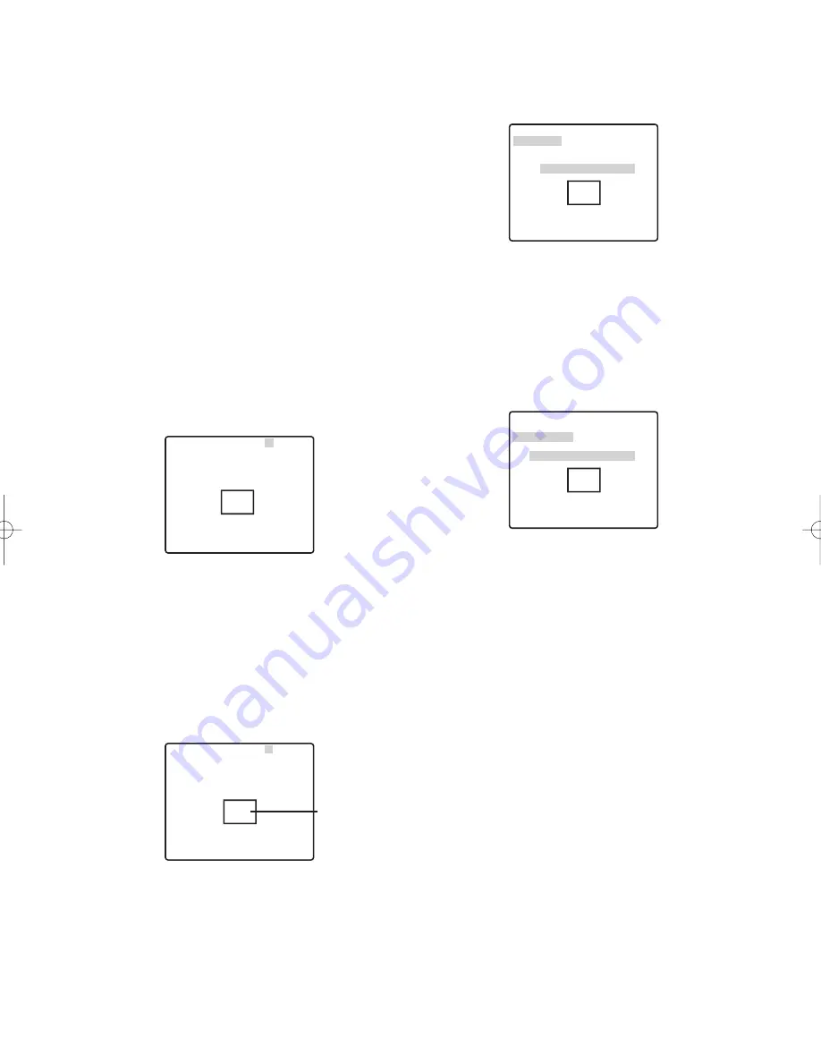
7. Move the cursor to 

PUSH SET to the right of

ZOOM/FOCUS, and then press the CAM (SET) button.
This will display the ZOOM/FOCUS setting menu. 

8. Move the joystick left, right, up and down to adjust

the position of the lens focus, and then press the
CAM (SET) button.  
This completes the adjustment procedure and
returns to the zone setting menu. 
Zoom can be set in a range of 1 to 10 magnifications.

9. Move the cursor to ZONE SCALE, and then tilt the

joystick left or right to change the size of the zone frame.
Shifting the setting towards the - side makes zone
frame smaller, while shifting towards the + side makes
it larger. Note, that the aspect ratio of the zone frame
is always 3:4. Also, the size of the zone frame that can
be set changes according to the zoom ratio. 

10. Move the cursor to SET, and then press the CAM

(SET) button. 
This completes the privacy zone setting procedure
and returns to the zone number selection menu. 
Selecting DEL instead of SET deletes the zone settings
and returns to the zone number selection menu. 

(9) Image Hold Setting (IMAGE HOLD)

Image hold causes the current picture to be frozen until
the camera finishes moving to a preset position. This
function comes in handy when using a network interface
unit for monitoring of camera images over a network. 

1. Move the cursor to IMAGE HOLD, and then tilt the

joystick left or right to toggle it on and off. 

ON

:

Maintains the last image until the camera
finishes moving to a preset position. 
However, the still image may be distorted
with the effect of panning or tilting.

OFF :

Picture being picked up by the camera
continues to be displayed as the camera
moves to a preset position. 

(8) Privacy Zone Setting (PRIVACY ZONE) 

The privacy zone function makes it possible to mask
specific areas of the scene (screen) from view. Up to
eight privacy zones can be configured.

Notes:

• Certain camera orientations can cause privacy

zone masked area to become visible.  

• The privacy zone function does not mask scene

areas during the initialization routine performed
immediately after camera power is turned on.

• The zone position may shift if the stabilizer settings

are change after setting the privacy zone. 

1. Move the cursor to PRIVACY ZONE, and then tilt the

joystick left or right to select a privacy zone setting.

ON (1) :

Turns on the privacy zone function.

ON (2) :

Turns on the privacy zone function. (Mosaic)

OFF

:

Turns off the privacy zone function.

Use the following steps to configure privacy zones. 

2. Move the cursor to PRIVACY ZONE, and then press

the CAM (SET) button. 
This will display the ZONE NUMBER selection menu.
The picture will be wide angle (WIDE) if there is no
privacy zone defined for the current zone number. 

3. Move the cursor to ZONE NUMBER, and then tilt

the joystick left or right to select the zone number (1
to 8) you want to configure.  
An asterisk (*) to the right of the a number indicates
that it already has a privacy zone configured for it.
Selecting such a zone number zooms the picture to
the zoom setting that was in effect when its privacy
zone settings were configured. 

4. Press the CAM (SET) button. 

This will display the zone setting menu. The
appearance of the menu depends on zone settings.

The currently configured zone frame will appear in
the center of the picture. 
Performing the remaining steps of this procedure
will delete the current zone frame and replace it
with the new zone frame that you configure. 

5. Move the cursor to 

PUSH SET to the right of

PAN/TILT, and then press the CAM (SET) button. 
This will display the PAN/TILT setting menu. 

-36-

  **ZONE NUMBER  1 /8** 

 RET TOP

PUSH SET

PUSH SET

 •••

I

•••

128

 -     +

PAN/TILT
ZOOM/FOCUS

ZONE SCALE
 SET DEL
 RET TOP

  **ZONE NUMBER  3 /8**

Zone frame

PUSH SET

PUSH SET

 •••

I

•••

128

 -     +

PAN/TILT
ZOOM/FOCUS

   U ZOOM D/L FOCUS R

ZONE SCALE
 SET DEL
 RET TOP

  **ZONE NUMBER  3 /8**

PUSH SET

PUSH SET

 •••

I

•••

128

 -     +

PAN/TILT
ZOOM/FOCUS

     U TILT D/L PAN R

ZONE SCALE
 SET DEL
 RET TOP

  ** ZONE NUMBER  3 /8**

 WV-CW964  05.10.18  11:09 AM  ページ36

Summary of Contents for Super Dynamic III WV-CW964

Page 1: ...Color CCTV Camera Operating Instructions Model No WV CW964 Before attempting to connect or operate this product please read these instructions carefully and save this manual for future use...

Page 2: ...ause harmful interference to radio communications Operation of this equipment in a residential area is likely to cause harmful interference in which case the user will be required to correct the inter...

Page 3: ...to your outlet consult an electrician for replacement of the obsolete outlet 10 Protect the power cord from being walked on or pinched particularly at plugs convenience receptacles and the point where...

Page 4: ...RODUCT BY THE USER THIS PUBLICATION COULD INCLUDE TECHNICAL INACCURACIES OR TYPOGRAPHICAL ERRORS CHANGES ARE ADDED TO THE INFORMATION HEREIN AT ANY TIME FOR THE IMPROVEMENTS OF THIS PUBLICATION AND OR...

Page 5: ...ory The system can be configured with up to 256 camera positions A particular camera position can be selected and viewed by entering the applicable preset number on the system controller 10 key pad Mo...

Page 6: ...down for example mounted on the floor may cause malfunction 10 Do not operate the camera beyond the specified temperature humidity or power source ratings Do not use the camera in an extreme environme...

Page 7: ...on one spot for a long period can cause deterioration of the CCD internal color filters and discoloration of the affected part Even if the camera position is changed from a fixed position the discolo...

Page 8: ...324 may cause an error and failure of the uploading process Self diagnosing Function If abnormal operation due to external noise or some other reason continues for more than 30 seconds the camera will...

Page 9: ...unication Parameters DIP Switch 1 15 CAMERA INSTALLATION 16 Mounting the Camera 16 Installing the brackets 18 Attach the brackets to the camera 18 Attach the front and rear sun shields provided to the...

Page 10: ...If cleaning the slip ring does not eliminate poor picture quality and noise it could mean that the slip ring has reached the end of its service life Contact a qualified service person or system instal...

Page 11: ...g temperature range 40 C to 50 C 40 F to 122 F In a motor vehicle on a boat or other areas subject to strong vibration This camera is not designed for use in a vehicle Near an air conditioner outlet o...

Page 12: ...ount of snow that collects on the dome cover depends on the quality and amount of the snow 3 Effects of dust and automobile exhaust Airborne dust and automobile exhaust from the location where the cam...

Page 13: ...ng toggles between 2 line and 4 line communication Use these switches to select the communication protocol being used 1 2 3 4 ON Terminator Communication Parameters 1 2 3 4 ON 4 line Communication 1 2...

Page 14: ...IP Switch 1 Unit Number DIP Switch 1 Unit Number 1 96 1 2 3 4 5 6 7 8 9 10 11 12 13 14 15 16 17 18 19 20 21 22 23 24 25 26 27 28 29 30 31 32 33 34 35 36 37 38 39 40 41 42 43 44 45 46 47 48 49 50 51 52...

Page 15: ...5 6 7 8 1 2 3 4 ON 5 6 7 8 1 2 3 4 ON 5 6 7 8 1 2 3 4 ON 5 6 7 8 1 2 3 4 ON 5 6 7 8 1 2 3 4 ON 5 6 7 8 1 2 3 4 ON 5 6 7 8 RS485 Communication Parameters DIP Switch 1 Configuring DIP Switch 1 as shown...

Page 16: ...To prevent the camera from falling use a mounting a bracket to which a safety wire can be attached 3 Installation Surface Caution Consult an expert on the load bearing capacity of the installation sur...

Page 17: ...t supplied 2 Fix the attachment pipe to the bracket 3 Thread cables through the bracket Connect cables referring to CONNECTIONS Warning Seal the cables with plastic or rubber tape to prevent it from b...

Page 18: ...e clamping the sun shield close the front and rear sun shields first latch the hook on the wire side and then do the other side Take care that the camera safety wire does not go on the inside 4 Align...

Page 19: ...nder 1200 meters in the case of 5C 2V 3 Be sure to connect the grounding cable to ground Alarm In Out Ratings Alarm In 5 V DC pull up input Drive capacity of at lease 0 2 mA required OFF 4 V DC minimu...

Page 20: ...individual conductors Prepare the individual conductors for clamping Use MOLEX band tool part number 57027 5000 for UL Style Cable UL1015 or 57026 5000 for UL Style UL1007 for clamping the contacts Af...

Page 21: ...7 Move the cursor to XON XOFF and then tilt the joystick left or right to select an XON XOFF setting The factory default setting is NOT USE NOT USE Disables X ON X OFF data flow control USE Enables X...

Page 22: ...a ID display on and off 2 Select ON or OFF and then press the CAM SET button The factory default setting is OFF 3 Use the joystick to move the cursor the character you want to input and then press the...

Page 23: ...hen press the CAM SET button This registers the position number setting and displays the preset setting menu this page To select a position number in the range of 033 to 064 move the cursor to 33 64 i...

Page 24: ...ng information that has been downloaded saved before some unforeseen damage or malfunction causes setting information in the camera to be lost However there may be some slight differences in images fr...

Page 25: ...been changed Do not operate the system controller when changing settings If you have selected either Japanese or Chinese as the language only the IDs and titles can be set in katakana or Chinese The L...

Page 26: ...ighter area to become washed out SUPER D 3 digitally combines an image that is set up for a clear view of bright areas with an image that is set up for a clear view of dark areas creating a final imag...

Page 27: ...shutter setting fluorescent lighting may cause flickering of the picture If this happens select OFF or 1 100 for the shutter speed setting AUTO is disabled when MANUAL is selected for light control AL...

Page 28: ...o zero crossing of the AC line phase If the AC line phase contains spike noise etc the vertical phase of the video output signal may be disturbed 7 White Balance WHITE BAL 1 Move the cursor to WHITE B...

Page 29: ...the joystick left to select the threshold illuminance level for switching between the color mode and the black and white mode The illuminance shown below is based on the assumption that the camera is...

Page 30: ...ng manual operation zoom operation cannot go beyond the zoom limit Optical zoom ranges from 1 to 30 magnifications while digital zoom is used for higher magnifications up to 300 The factory default se...

Page 31: ...in the range of 033 to 064 move the cursor to 33 64 in the lower left corner of the menu and then press the CAM SET button Preset numbers set subsequently are the same Notes An asterisk to the right o...

Page 32: ...the number of the scene file whose settings you want to configure 2 Press the CAM SET button This will display the scene file setting menu The following items can be set on the Scene file settings me...

Page 33: ...shown below 3 Home Position Setting HOME POSITION A currently configured preset position can be designated as the home position Pressing the HOME button of the system controller will cause the camera...

Page 34: ...ZOOM FOCUS is performed if AUTO PAN is operating and PAN TILT does SEQ SORT PATROL or AUTO TRACK movement Note however that that the contents of the setting menu do not change To return to the auto mo...

Page 35: ...PATROL The patrol function remembers manual operations for later automatic playback when they are needed 1 Aim the camera with the menu closed at the start point of the routine you want it to remember...

Page 36: ...ecific areas of the scene screen from view Up to eight privacy zones can be configured Notes Certain camera orientations can cause privacy zone masked area to become visible The privacy zone function...

Page 37: ...12 Area Title Setting AREA TITLE The area title function lets you display a direction indicator that appears in the picture to indicate the direction of the location being shown on the screen Text ca...

Page 38: ...to select an area title display position and then press the MON ESC button This registers the area title display position and returns to the area title NESW setting menu Note The area title is always...

Page 39: ...sk the areas of the screen that you do not want the motion detector to monitor for movement To mask screen areas use the same procedure as step 5 under SUPER D 3 Super Dynamic 3 on page 26 After confi...

Page 40: ...e preset alarm will output an alarm from the video output port or alarm output connector when the camera completes a move to a preset position An alarm is output in the following cases When the self r...

Page 41: ...d to the camera settings and are kept even after the camera is turned on again PATROL1 S 4 S displays only the set number of patrol routines page 35 6 Move the cursor to CNT CLS 1 and then tilt the jo...

Page 42: ...ys for the alarm display are shown in the table below Notes Use a shortcut page 47 to switch between displaying or not displaying the pan tilt zoom positions during pan tilt and zoom operation and typ...

Page 43: ...PUSH SET to the right of REFRESH and then press the F3 button The refresh function corrects the camera position when it starts to deviate from the preset positions 5 Returning Camera Settings to Their...

Page 44: ...select settings First display the scene select setting menu 1 Display the setup menu page 22 move the cursor to SCENE SELECT O and then press the CAM SET button This will display the scene select set...

Page 45: ...factory default password is 123 4 Press the CAM SET button This returns to the setup menu and toggles PASSWORD LOCK on or off The password input screen will reappear if you press the CAM SET button a...

Page 46: ...reen again for verification Note that you cannot register the new password by pressing the MON ESC button 6 Input the new 3 digit password again by moving the cursor to each of the applicable numbers...

Page 47: ...TO PAN speed one step 6 8 CAM FUNCTION Decreases AUTO PAN speed one step 6 9 CAM FUNCTION Sets AUTO PAN start point 7 0 CAM FUNCTION Sets AUTO PAN end point 7 1 CAM FUNCTION AUTO MODE OFF 7 2 CAM FUNC...

Page 48: ...N BW AUTO switching time 10 seconds 1 9 1 CAM FUNCTION BW AUTO switching time 30 seconds 1 9 2 CAM FUNCTION BW AUTO switching time 60 seconds 1 9 3 CAM FUNCTION BW AUTO switching time 300 seconds 1 9...

Page 49: ...with your system controller Is the lens iris closed Execute the iris reset from the system controller you are using 26 27 Is the camera set up for a fixed shutter speed 27 White picture Is FIX selecte...

Page 50: ...on Check the setting of this mode 29 Frequent switching between the color and the black and white modes Adjust the black and white mode switching level and the duration time setting 29 White specks in...

Page 51: ...camera connected correctly See the operating instructions that come with the system controller you are using The camera has a pan limit function Check the PAN LIMIT settings 34 The motor or lens may b...

Page 52: ...ion 33 Problem Cause and Recommended Action Reference Pages Camera position is different from the preset position setting Perform REFRESH from the special setup menu 43 Picture is different from the p...

Page 53: ...Dimensions 239 mm D 395 5 mm H 11 3 8 D 15 37 64 H Weight Approximately 4 7 kg 10 4 lbs Finish Camera Die cast aluminum baked on coating Paint color Fine sliver Sun shield ASA resin coated Paint colo...

Page 54: ...l MANUAL Shutter OFF 1 60 AUTO 1 100 1 250 1 500 1 1000 1 2000 1 4000 1 10000 Electronic Sensitivity Enhancement 32X max AUTO or FIX Auto Mode OFF SEQ SORT AUTO PAN PATROL AUTO TRACK Auto Pan Key SEQ...

Page 55: ...55...

Page 56: ...any of Panasonic Corporation of North America Security Systems www panasonic com security For customer support call 1 877 733 3689 Executive Office Three Panasonic Way 2H 2 Secaucus New Jersey 07094 Z...

Reviews: