9
5 Disassembly and Assembly Instructions
5.1.
Replacing the switch assembly.
1
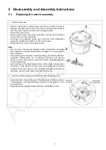
Remove the base.
• Place a rubber pad or similar thing under the rice cooker to prevent
damage, and open the lid of the rice cooker, and place the bottom of
the rice cooker upward, as shown in the diagram right.
• Pull out the power cord.
• Remove the fixing screws of the underframe (on the side) and those
at the bottom (on the underside).
• As shown in the diagram, gently pry at the slot of the underframe
edge with a slotted screwdriver, to remove the base.
• Disassemble the wires of the power socket.
Note:
• Do not remove the base by tapping it with a screwdriver, otherwise
the screwdriver contacted parts will be damaged. You must use the
above method.
• Upon pulling out connectors and similar things, just directly pull them
outwards. Pulling them out in different directions will impose
pressure on the components connected to them, to cause damages
to the components.
• Upon pulling out the fastening terminals at the chuck, please press
them down in the direction of the arrow, while pulling the lock catch
outward. Press them down in the direction indicated by the arrow,
otherwise you will not be able to pull out the terminals.
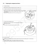
2
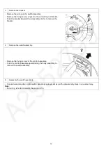
Disconnect the temperature limiter from the connecting rod.
• Gently bend the sheet at the end of the temperature limiter as shown
in the diagram, and fold it into the slot shape at the junction of the
connecting rod.
• Separate the temperature limiter from the connecting rod slot.
Summary of Contents for SR-JP185WVA-US
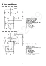
Page 4: ...4 2 Schematic Diagram 2 1 For 120V 650W model 2 2 For 220V 400W model ...
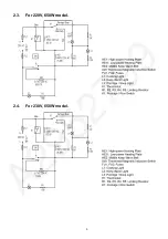
Page 5: ...5 2 3 For 220V 650W model 2 4 For 230V 650W model ...
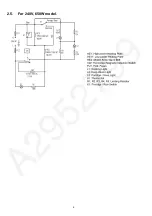
Page 6: ...6 2 5 For 240V 650W model ...
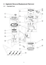
Page 15: ...15 6 Exploded View and Replacement Parts List 6 1 Exploded View ...
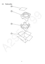
Page 16: ...16 6 2 Packing View ...

