3
SR-GA421/SR-GA281/SR-GA721
L
N
MICA HEATER ASS’Y
CAST HEATER
LAMP RESIST.
T.F.
INPUT
SWITCH
LAMP RESIST.
KEEP WARM NEON LAMP
(BIG)
(SMALL)
E
Green
RICE COOKING NEON LAMP
Lamp Lead Wire A (Orange)
Lead Wire (Orange)
Lamp Lead Wire C (Brown)
Twist one time
Lamp Lead Wire B (Gray)
Lever Earth Lead Wire (Green)
Silicone Tube (Blue)
N
Twist two time
Thermal Fuse Wire (Gray)
Switch Lead Wire (Blue)
Cord Wire Earth (Green)
Silicone Tube (Green)
Silicone Tube (Brown)
Cord Bush
10˚ ±5
˚
Thermal Fuse Wire (Brown)
N
Cord Bush
Silicone Tube (Blue)
Silicone Tube (Brown)
After ass’y, Mica Heater Ass’y must not overlie
the Outer Case of Center Thermostat.
Water guard
Cord Wire Earth (Green)
Silicone Tube (Green)
Thermal Fuse Wire (Blue)
Lever Earth Lead Wire (Spiral Green)
Wiring Lead Wire (Brown)
Lamp Lead Wire A (Red)
Lamp Lead Wire C (Brown)
Twist one time
Thermal Fuse Wire (Gray)
Lamp Lead Wire B (Gray)
After assembly Mica Heater case
Must no touch the terminal of cast heat.
Glass tape 20 x 20 mm.
After ass’y, gap between terminal and mica heater case must be more than 4 mm.
10˚ ±5
˚
Cast Heater
Lamp Resistor
Lamp Resistor
Switch
Keep Warm Neon Lamp
Rice Cooking Neon Lamp
Gray
Input
Blue
Brown
N
L
E
Green
Mica Heater Ass’y
T.F.
T.F.
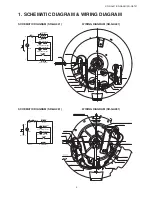
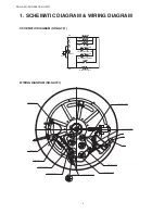
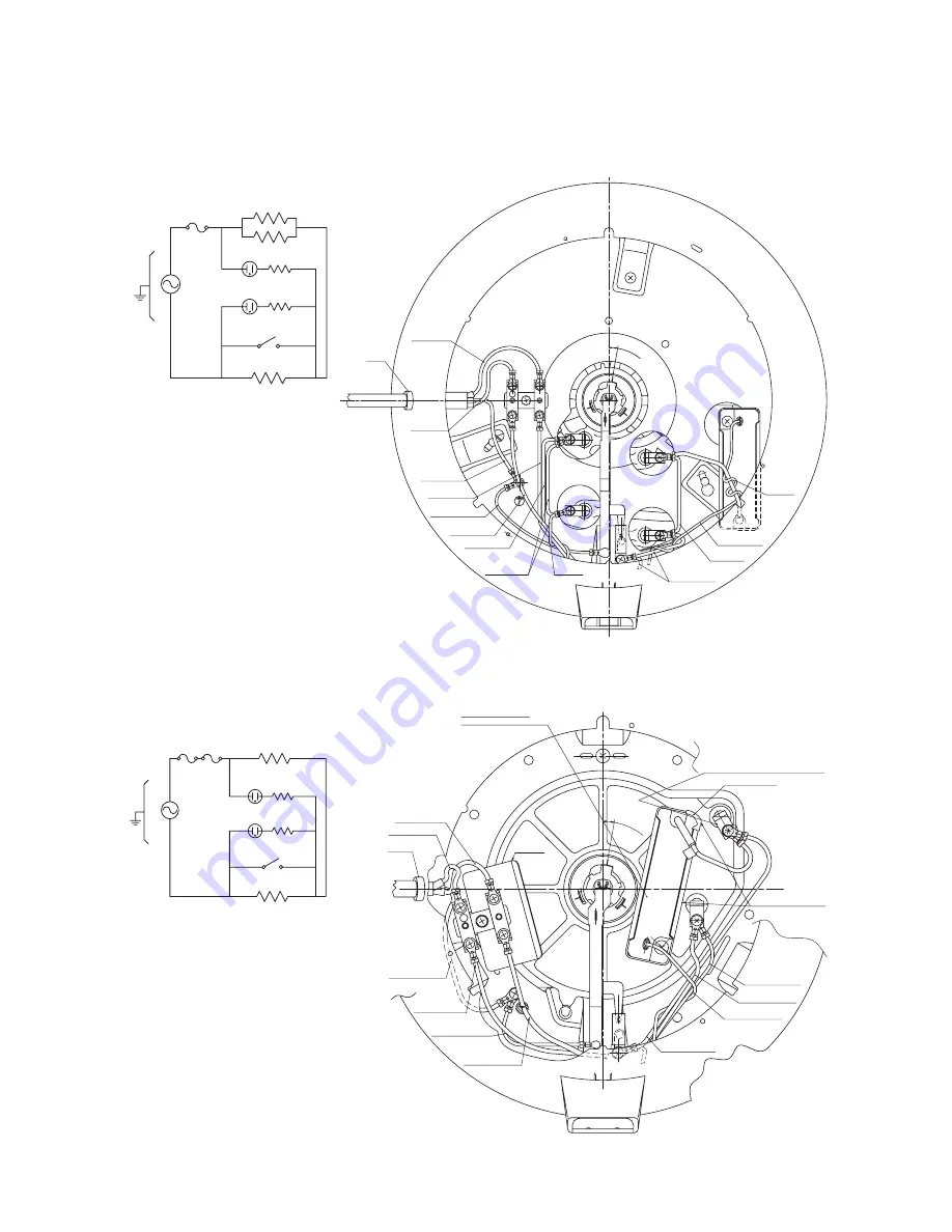
1. SCHEMATIC DIAGRAM & WIRING DIAGRAM
SCHEMATIC DIAGRAM (SR-GA421)
WIRING DIAGRAM (SR-GA421)
SCHEMATIC DIAGRAM (SR-GA281)
WIRING DIAGRAM (SR-GA281)


