Panasonic SC-HT540 Setup Manual Download Page 8

8

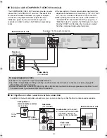
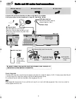
Television with COMPONENT VIDEO IN terminals

The COMPONENT VIDEO OUT terminals provides a purer 
picture than the S-VIDEO OUT terminal. These terminals 
can be used for either interlaced or progressive output. 
Connection using these terminals outputs the color 
difference signals (P

B

/P

R

) and luminance signal (Y) 

separately in order to achieve high fidelity in reproducing 
colors.

The description of the component video input terminals 
depends on the television or monitor (e.g. Y/P

B

/P

R

, Y/B-Y/

R-Y, Y/C

B

/C

R

). Connect to terminals of the same color.

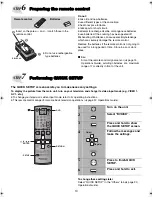
When making this connection, select “Video/YPbPr” or 
“S-Video/YPbPr” from QUICK SETUP (

page 10). If 

“RGB/No Output” is selected, the RGB signal is output 
from the SCART (AV) terminal, but no signal is output 
from the component video output terminals.

Set Top Box or video cassette recorder connection

To enjoy progressive video

Connect to a progressive output compatible television. 

Set “Video Output Mode” to “480p” or “576p”, and then follow the instructions on the menu screen (

page 26, 

Picture Menu, Operations Guide).

Panasonic televisions with 625 (576)/50i·50p, 525 (480)/60i·60p input terminals are progressive compatible. Consult 

the manufacturer if you have another brand of television.

P

B

P

R

Y

R

L

AUX

AUX

  INTERLACE)

(PROGRESSIVE/

COMPONENT VIDEO OUT

VIDEO

VIDEO

OUT

OUT

S-VIDEO

S-VIDEO

OUT

OUT

AV

r

s

VIDEO IN

S-VIDEO

IN

COMPONENT

VIDEO IN

P

R

P

B

Y

Television

(not included)

Back of the main unit

Video cables

(not included)

See page 7 for the audio connection.

RF IN

RF OUT

RF IN

AUDIO

OUT

L

R

VIDEO IN

AUDIO

IN

VIDEO OUT

VIDEO

VIDEO

OUT

OUT

S-VIDEO

OUT

  INTERLACE)

(PROGRESSIVE/

COMPONENT VIDEO OUT

P

B

P

R

Y

L

R

AUX

AUX

L

R

Television

(not included)

Video cable

(not included)

Back of the main unit

Audio cable 

(not included)

You can use the scart cable 
connection (

page 6) 

instead of this connection.

RF cable

(not included)

Set Top Box or 
video cassette recorder

(not included)

To the 
aerial

In addition to the audio and video connections, you can also connect your Set Top Box or video cassette recorder.

EB-setup guide.fm  Page 8  Saturday, March 11, 2006  8:49 AM

Summary of Contents for SC-HT540

Page 1: ...setup are completed Please see the Operations Guide for playback operations STEP1 Assembling the speakers STEP2 Positioning the speakers STEP3 Speaker connections STEP4 Audio and video connections ST...

Page 2: ...ugh the hole and then pull the rest of the cable through the base 2 Attach the stand to the base while gently pulling on the end of the speaker cable 2 Secure the stand to the base 3 Attach the speake...

Page 3: ...rete wall or a surface that may not have strong enough support Improper attachment may result in damage to the wall or speakers Speaker Stand Cover plate Remove before attaching the speaker and keep f...

Page 4: ...ation To allow for proper ventilation and to maintain good airflow around the main unit position it with at least 5 cm of space on all sides Do not block the ventilation holes of the main unit Center...

Page 5: ...so may lead to damage to the amplifier and or the speakers and may result in the risk of fire Consult a qualified service person if damage has occurred or if you experience a sudden change in performa...

Page 6: ...dio from your television through your home theater system Refer to Operating other equipment page 37 Operations Guide Connecting to a television with SCART AV terminal STEP4 Audio and video connection...

Page 7: ...DEO OUT OUT AV r s R L AUX AUX VIDEO VIDEO OUT OUT AUDIO OUT L R VIDEO IN AUDIO IN VIDEO OUT This audio connection will enable you to play audio from your television through your home theater system R...

Page 8: ...vision Set Video Output Mode to 480p or 576p and then follow the instructions on the menu screen page 26 Picture Menu Operations Guide Panasonic televisions with 625 576 50i 50p 525 480 60i 60p input...

Page 9: ...ld mains socket AC 230 240 V 50 Hz AC mains lead Main unit AM loop antenna Stand the antenna up on its base Place the antenna where reception is best Keep loose antenna cable away from other wires and...

Page 10: ...necessary settings To display the picture from the main unit turn on your television and change its video input mode e g VIDEO 1 AV 1 etc To change your television s video input mode refer to its oper...

Page 11: ...11 MEMO...

Page 12: ...Matsushita Electric Industrial Co Ltd Web Site http www panasonic co jp global RQT8723 B F0306NK0 p...

Reviews: