background image

5

Notes on speaker use

You can damage your speakers and shorten their useful 
life if you play sound at high levels over extended periods.

Reduce the volume in the following cases to avoid 
damage:
– When playing distorted sound.
– When the speakers are reverberating due to a record 

player, noise from FM broadcasts, or continuous signals 
from an oscillator, test disc, or electronic instrument.

– When adjusting the sound quality.
– When turning the unit on or off.

If irregular coloring occurs on your television

The front and center speakers are designed to be used 
close to a television, but the picture may be affected with 
some televisions and setup combinations.

If this occurs, turn the television off for about 
30 minutes.

The demagnetizing function of the television should correct 
the problem. If it persists, move the speakers further away 
from the television.

Caution

The main unit and supplied speakers are to be used 
only as indicated in this setup. Failure to do so may 
lead to damage to the amplifier and/or the speakers, 
and may result in the risk of fire. Consult a qualified 
service person if damage has occurred or if you 
experience a sudden change in performance.

Do not attempt to attach these speakers to walls using 
methods other than those described in this manual.

STEP

3

Speaker connections

4

4

2

2

6

6

5

3

5

3

1

1

SURR

OUND

Rch

Rch

SURR

OUND

Rch

Rch

FR

ONT

W

OOFER

SUB

Lch

Lch

Lch

CENTER

Lch

SURR

OUND

SURR

OUND

FR
ONT

SUB

W

OOFER

FR
ONT

FR

ONT

CENTER

FRONT

Lch

Rch

SURROUND

Rch

FRONT

2

Rch

FRONT

FRONT

Lch

Rch

SURROUND

CENTER

5

CENTER

5

Lch

SURROUND

Lch

SURROUND

2

1

1

4

3

3

SUB

WOOFER

6

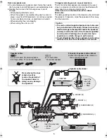
Be careful not to cross 
(short-circuit) or 
reverse the polarity of 
the speaker wires as 
doing so may damage 
the speakers.

2 sheets of speaker cable stickers

Attach the speaker-cable stickers to 
make connection easier.

Speaker cable sticker

2

 FRONT (R)

1

 FRONT (L)

4

 SURROUND (R)

3

 SURROUND (L)

5

 CENTER

Main unit

Insert the wire fully.

i

: White

j

: Blue

Push!

6

 SUBWOOFER

Speaker cables

[HT540]

1

k

short cable: For center speaker

2

k

long cables: For surround speakers

Push!

[HT990]

1

k

short cable: 

For center speaker

Insert the 
wire fully.

i

: White

j

: Blue

EB-setup guide.fm  Page 5  Tuesday, February 28, 2006  9:49 AM

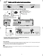
Summary of Contents for SC-HT540

Page 1: ...setup are completed Please see the Operations Guide for playback operations STEP1 Assembling the speakers STEP2 Positioning the speakers STEP3 Speaker connections STEP4 Audio and video connections ST...

Page 2: ...ugh the hole and then pull the rest of the cable through the base 2 Attach the stand to the base while gently pulling on the end of the speaker cable 2 Secure the stand to the base 3 Attach the speake...

Page 3: ...rete wall or a surface that may not have strong enough support Improper attachment may result in damage to the wall or speakers Speaker Stand Cover plate Remove before attaching the speaker and keep f...

Page 4: ...ation To allow for proper ventilation and to maintain good airflow around the main unit position it with at least 5 cm of space on all sides Do not block the ventilation holes of the main unit Center...

Page 5: ...so may lead to damage to the amplifier and or the speakers and may result in the risk of fire Consult a qualified service person if damage has occurred or if you experience a sudden change in performa...

Page 6: ...dio from your television through your home theater system Refer to Operating other equipment page 37 Operations Guide Connecting to a television with SCART AV terminal STEP4 Audio and video connection...

Page 7: ...DEO OUT OUT AV r s R L AUX AUX VIDEO VIDEO OUT OUT AUDIO OUT L R VIDEO IN AUDIO IN VIDEO OUT This audio connection will enable you to play audio from your television through your home theater system R...

Page 8: ...vision Set Video Output Mode to 480p or 576p and then follow the instructions on the menu screen page 26 Picture Menu Operations Guide Panasonic televisions with 625 576 50i 50p 525 480 60i 60p input...

Page 9: ...ld mains socket AC 230 240 V 50 Hz AC mains lead Main unit AM loop antenna Stand the antenna up on its base Place the antenna where reception is best Keep loose antenna cable away from other wires and...

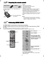
Page 10: ...necessary settings To display the picture from the main unit turn on your television and change its video input mode e g VIDEO 1 AV 1 etc To change your television s video input mode refer to its oper...

Page 11: ...11 MEMO...

Page 12: ...Matsushita Electric Industrial Co Ltd Web Site http www panasonic co jp global RQT8723 B F0306NK0 p...

Reviews: