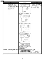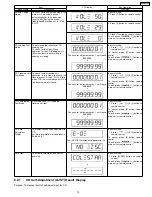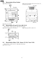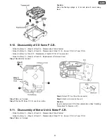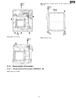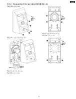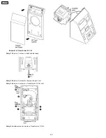
Below is the procedures for this mode.
Step 1: Enter into Doctor mode (For more information refer to section 8.2 on key operation to enter into this mode).
Step 2: When [
], [1] & [4] are pressed at the doctor mode, the following shall be displayed for 3s. The result shall correspond
to the condition met as shown in the table below:
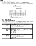
8.3. Error Code Table 1
8.3.1. Mechanism Error Code Table
Self-Diagnosis Function provides information on any problems occuring for the unit and its respective components by displaying
error codes. These error code such as U**, H** and F** are stored in memory and held unless it is cleared.
The error code is automatically display after entering into self-diagnostic mode.
Error Code
Diagnosis Contents Description of error
Automatic FL Display
Remarks
F15
CD REST SW
abnormal
CD
traverse
position
initial setting operation
failsafe
counter
(1000ms)
waiting
for
REST SW to turn on.
Error no. shall be clear
by force or during cold
start.
For CD unit.(For traverse).
Press [
] on main unit for next error.
F26
Communication
between CD servo
LSI and micro-p
abnormal.
CD
function
DTMS
command, after system
setting, if SENSE = “L”
cannot
be
detected.
Memory shall contain
F26code. After power
on, CD function shall
continue, error display
shall be “NO DISC”.
Error no. shall be clear
by force or cold start.
For CD unit.(For traverse).
Press [
] on main unit for next error.
F76
Abnormality in the
output voltage of
stabilized power
supply.
In
normal
operation
when
“DCDET”
is
detected “L” (IOIO) for
two consecutive times,
this error code will be
displayed for 2s & after
PCONT will be turned to
“L” (Low).
Press [
] on main unit for next error.
16
SC-EN33PC
Summary of Contents for SC-EN33PC
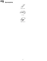
Page 10: ...6 Accessories Remote Control AC Cord FM AM Antenna 10 SC EN33PC ...
Page 12: ...7 3 Connection 12 SC EN33PC ...
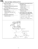
Page 30: ...11 1 Check and Repair of CD Servo P C B 30 SC EN33PC ...
Page 33: ...12 2 CD Servo P C B 12 3 Motor P C B 12 4 Panel P C B 12 5 Tuner P C B 33 SC EN33PC ...
Page 34: ...12 6 Waveform Chart 34 SC EN33PC ...
Page 35: ...13 Wiring Connection Diagram 35 SC EN33PC ...
Page 36: ...36 SC EN33PC ...
Page 37: ...14 Block Diagram 14 1 CD Servo SC EN33PC 37 ...
Page 38: ...14 2 Tuner SC EN33PC 38 ...
Page 39: ...14 3 Main 1 2 Transformer Sensor SC EN33PC 39 ...
Page 40: ...14 4 Main 2 2 Panel LED Power Switch Tact Switch Switch Motor SC EN33PC 40 ...
Page 42: ...42 SC EN33PC ...
Page 44: ...16 1 A CD Servo Circuit SC EN33PC 44 ...
Page 45: ...16 2 B Tuner Circuit SC EN33PC 45 ...
Page 46: ...16 3 C Main Circuit SC EN33PC 46 ...
Page 47: ...SC EN33PC 47 ...
Page 48: ...SC EN33PC 48 ...
Page 50: ...16 5 I Motor Circuit J Sensor Circuit K Transformer Circuit SC EN33PC 50 ...
Page 52: ...17 1 A CD Servo P C B B Tuner P C B SC EN33PC 52 ...
Page 53: ...17 2 C Main P C B SC EN33PC 53 ...
Page 57: ...20 Exploded Views 20 1 Cabinet Parts Location SC EN33PC 57 ...
Page 58: ...SC EN33PC 58 ...
Page 59: ...20 2 Packaging SC EN33PC 59 ...
Page 60: ...SC EN33PC 60 ...

