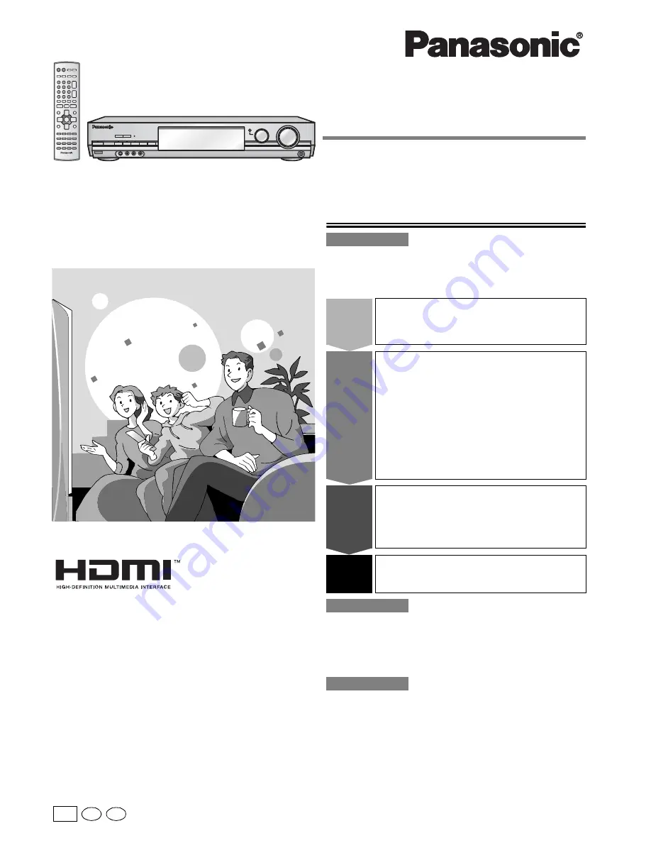
background image

PP

Model No.

 SA-XR70

En Cf

RQT7523-Y

H0804RT0

Operating Instructions

AV Control Receiver

Dear customer

Thank you for purchasing this product. 
Before connecting, operating or adjusting this product, please read these
instructions completely. 
Please keep this manual for future reference.

Table of contents

IMPORTANT SAFETY INSTRUCTIONS ................................. 2
Listening caution.................................................................... 3
Supplied accessories ............................................................ 3 
The remote control ................................................................ 3 

Control guide ........................................................................ 18
The radio ............................................................................... 20 
Audio settings....................................................................... 22
Other functions..................................................................... 25
Making a recording............................................................... 25

Specifications ....................................................................... 26
Product Service .................................................................... 26
Maintenance.......................................................................... 26
Warranty (U.S.A.) .................................................................. 27
Troubleshooting guide ......................................................... 28

Before use

Step 

1

Home Theater connections.... 4

• DVD player/TV or monitor......................(4)

• Speakers/AC power supply cord ...........(5)

Step 

2

Other connections .................. 6

• Bi-wiring connection/

Using speaker terminal B ......................(6)

• Having fun with DVDs using HDMI


connections/

Antennas ...........................(7)

• DVD recorder/VCR/TV or monitor/

Cable box or satellite receiver etc. ........(8)

• Video camera etc. .................................(9)

• CD player/CD recorder/Tape deck/

Using the SECOND AUDIO OUT ........(10)

Step 

3

Settings.................................. 11

• Customizing your receiver

A. Using the On Screen Display  .......................... (12)

B. Using the Multi control...................................... (14)

• Adjusting speaker output level.............(15)

Step


4

Basic operations................... 16

• Sound modes ......................................(16)

Operations

Reference

Summary of Contents for SA-XR70S

Page 1: ...5 Specifications 26 Product Service 26 Maintenance 26 Warranty U S A 27 Troubleshooting guide 28 Before use Step 1 Home Theater connections 4 DVD player TV or monitor 4 Speakers AC power supply cord 5 Step 2 Other connections 6 Bi wiring connection Using speaker terminal B 6 Having fun with DVDs using HDMI connections Antennas 7 DVD recorder VCR TV or monitor Cable box or satellite receiver etc 8 ...

Page 2: ...EN CAUTION TO REDUCE THE RISK OF ELECTRIC SHOCK DO NOT REMOVE SCREWS NO USER SERVICEABLE PARTS INSIDE REFER SERVICING TO QUALIFIED SERVICE PERSONNEL The lightning flash with arrowhead symbol within an equilateral triangle is intended to alert the user to the presence of uninsulated dangerous voltage within the product s enclosure that may be of sufficient magnitude to constitute a risk of electric...

Page 3: ...r purchase The remote control Insert so the poles and match those in the remote control Do not use rechargeable type batteries Aim at the sensor avoiding obstacles at a maximum range of 7 m 23 feet directly in front of the unit Keep the transmission window and the unit s sensor free from dust Operation can be affected by strong light sources such as direct sunlight and the glass doors on cabinets ...

Page 4: ...front center and surround speakers should be placed at approximately the same distance from the seating area The angles in the diagram are approximate White L Red R 75Ω GND LOOP EXT FM ANT AM ANT IN CD L R REC OUT PLAY IN TAPE LOOP ANT GND IN TV DVR VCR1 OUT IN OUT OPTICAL TV IN OPTICAL1 OPTICAL2 DVR IN COAXIAL2 CD IN OUT IN DVR VCR1 MONITOR OUT TV MONITOR OU Y PB P IN IN TV DVD D S VIDEO DIGITAL ...

Page 5: ...y performance Placement near a corner can increase the apparent output level but can result in unnatural bass Cable Speaker terminals Twist the wire FRONT Other terminals Note If using 4 mm plugs Do not short circuit Peripheral equipment and cables sold separately unless otherwise indicated To connect equipment refer to the appropriate operating instructions Front right Front left Surround right S...

Page 6: ...ss 2 Wiring R L LF BI WIRE FRONT B Front right speaker Front left speaker HF terminals LF terminals HF terminals LF terminals Step 2 Using speaker terminal B For connection to a second pair of speakers Use the A terminals to enjoy multi channel sound If SPEAKERS B is selected play will be 2 channel only For a multi channel source 2CH MIX mode will be automatically selected Cable Speaker terminals ...

Page 7: ...R VCR1 Y PB PR Y PB PR TV IN S VIDEO DVD IN COMPONENT VIDEO FRONT B CENTER SURROUND SPEAKERS 6 8Ω HAUT PARLEURS AC IN COAXIAL1 IN DVD VIDEO MONITOR OUT IN TV FRONT A DVD IN OUT SUBWOOFER R L R L BACK R L Class 2 Wiring BI WIRE HF LF DIGITAL DVD IN OUT TV HDMI AV IN DVD HDMI AV OUT Changing the HDMI input settings You can change the input setting for the HDMI terminal á pages 12 or 14 IN CD L R REC...

Page 8: ...IN IN TV DVD DVR VCR1 Y PB PR Y PB PR TV IN S VIDEO DVD IN COMPONENT VIDEO CENTER SUBWOOFER SURROUND FRONT DVD DVD 6CH COAXIAL1 IN DVD MONITOR OUT IN TV FRO DVD IN OUT SUBWOOFER R SECOND AUDIO OUT HDMI DVD IN OUT DIGITAL OPTICAL2 DVR IN OUT IN DVR VCR1 DVR VCR1 OUT IN AUDIO VIDEO DIGITAL AUDIO OUT VIDEO OUT VIDEO IN AUDIO OUT AUDIO IN 75Ω GND LOOP EXT FM ANT AM ANT IN CD L R REC OUT PLAY IN TAPE L...

Page 9: ...NENT VIDEO IN PR COMPONENT VIDEO IN PB COMPONENT VIDEO IN Y S VIDEO OUT S VIDEO IN LOOP ANT GND DVR VCR1 OUT IN OUT OPTICAL TV IN OPTICAL1 OPTICAL2 DVR IN COAXIAL2 CD IN OUT IN DVR VCR1 MONITOR OUT TV MONITOR OUT Y PB PR IN IN TV DVR VCR1 Y PB PR TV IN FRONT B CENTER SURROU SPEAKERS 6 8Ω HAUT PARLEURS DIGITAL CENTER SUBWOOFER SURROUND FRONT DVD DVD 6CH AUDIO COAXIAL1 IN DVD VIDEO MONITOR OUT IN TV...

Page 10: ... TV DVD DVR VCR1 Y PB PR Y PB PR TV IN S VIDEO DVD IN COMPONENT VIDEO CENTER SUBWOOFER SURROUND FRONT DVD DVD 6CH AUDIO COAXIAL1 IN DVD VIDEO MONITOR OUT IN TV FRONT DVD IN OUT SUBWOOFER R SECOND AUDIO OUT HDMI DVD IN OUT OUT OPTICAL DIGITAL DIGITAL IN 75Ω GND LOOP EXT FM ANT AM ANT IN CD L R LOOP ANT GND IN TV DVR VCR1 OUT IN OUT OPTICAL TV IN OPTICAL1 OPTICAL2 DVR IN COAXIAL2 CD IN OUT IN DVR VC...

Page 11: ...tically detects the input signal and plays When the signal is connected to the HDMI terminal the input signal from the HDMI terminal takes priority DVD or DVR only ANALOG Fixes the input signal to analog and plays DIGITAL Fixes the input signal to HDMI DVD or DVR only OPT and COAX digital and play PCM FIX Fixes the input signal to PCM and plays Setting item Description On Screen Display Multi cont...

Page 12: ...M FIX mode is on the unit cannot process other signals This may cause noise to be output Select another mode in this case The PCM FIX mode remains as set even if the power is turned off With the PCM FIX mode is on you cannot play multi channel sound Play is fixed as 2 channel 1 u t y i 2 3 4 5 6 7 8 9 DISC 0 10 RECEIVER AV SYSTEM TV CD TAPE MONITOR DVD RECORDER VCR CH VOLUME DIRECT TUNING TUNER BA...

Page 13: ...L C R LS RS SB 5 L C R LS RS q r w ENTER e 6 YES Speakers Subwoofer Digital Input Input Mode OPT 1 OPT 2 DVR DVD CD TV COAX1 COAX2 HDMI DVD q r w ENTER e q r w ENTER e OPT 2 DVR DVD CD TV COAX1 COAX2 HDMI DVD OPT 1 q r w ENTER e q r w ENTER e INPUT ENTER AUTO AUTO MODE DVR DVD CD TV AUTO AUTO q r w ENTER e INPUT ENTER AUTO MODE DVR DVD CD TV AUTO AUTO AUTO q r w ENTER e q r w ENTER e SMALL SMALL S...

Page 14: ...M FIX mode remains as set even if the power is turned off With the PCM FIX mode is on you cannot play multi channel sound Play is fixed as 2 channel SPEAKERS A B 8 6 1CH DECODING VCR 2 PHONES MULTI CONTROL INPUT SELECTOR VOLUME DOWN UP PUSH ENTER BI AMP BI WIRE VIDEO IN AUDIO IN L R S VIDEO IN MULTI CONTROL PUSH ENTER INPUT SELECTOR SPEAKERS A B BI WIRE POWER 8 1 u t y i 2 3 4 5 6 7 8 9 DISC 0 10 ...

Page 15: ...level of the front speakers Adjust center surround and surround back output to the same apparent level as the front speakers For SW subwoofer you can select MIN for minimum output a level between 1 and 19 or MAX for maximum output Adjust subwoofer output so it is balanced with that from the front speakers Subwoofer output is easily influenced by the source You can also change its level while playi...

Page 16: ...s of the direction you are facing MONO Best suited for older monaural audio movies To cancel Press STEREO 2CH MIX OFF 6 1CH DECODING mode This mode uses the surround back speaker to create a realistic sound field It is especially effective when playing DTS ES and Dolby Digital Surround EX but can be used with other DTS and Dolby Digital sources as well as Dolby Pro Logic Ⅱx DTS NEO 6 and SFC This ...

Page 17: ... stereo 2CH MIX mode When multi channel sources are played in this mode the sounds intended for the other speaker channels are played through the front speakers To cancel Press STEREO 2CH MIX OFF Notes on sound modes Dolby Pro Logic Ⅱx Dolby Pro Logic Ⅱ DTS NEO 6 and SFC modes remain in effect until you change them To cancel Press STEREO 2CH MIX OFF The 2CH MIX mode remains in effect until you cha...

Page 18: ... Avoid listening for prolonged periods of time to prevent hearing damage Turn the speakers off when using the headphones Display SPEAKERS Speaker indicators Sound is output from speakers connected to the front A surround and center terminals Sound is output only from speakers connected to the front B terminals Sound is output from speakers connected to the front A and B terminals Sound is output f...

Page 19: ...FER For selecting subwoofer level CENTER FOCUS For turning on the center focus mode MULTI REAR For turning on the multi rear surround mode STEREO 2CH MIX OFF For selecting STEREO or 2CH MIX mode To cancel surround effect PL Ⅱx Select MOVIE DOLBY EX MUSIC or GAME when Dolby Pro Logic Ⅱx mode or Dolby Pro Logic Ⅱ mode is on DTS NEO 6 For selecting a DTS NEO 6 mode CINEMA or MUSIC SFC For selecting a...

Page 20: ... to this mode This may change the volume but noise will also be reduced 1 Select OPTION 2 Select B PROOF 3 Select MODE A or MODE B For your reference Improving reception DVD players can interfere with radio reception Turn the DVD player off or move it further away from the antennas if this occurs Beat proof mode Changing these settings also changes the A D attenuator settings which are linked á pa...

Page 21: ... the channel STORED is displayed Preparation Set the station signal you want to set as a preset Preset the stations one at a time FM stations can also be preset in the MONO mode To continue presetting press TUNE 2 or 1 to tune another station from step For your reference Even if the AC power supply cord is disconnected from the household AC outlet the stations remain in the memory for approximatel...

Page 22: ...CT 2 For tracks with a variety of tempos jazz EFFECT 3 For slow tracks classical EFFECT 4 For compressed audio signals OFF The re master processing is off Multi source re master cannot be used in the following cases When Dolby Pro Logic Ⅱx DTS NEO 6 SFC or 6 1CH DECODING is on For your reference The bass synthesizer or multi source re master cannot be used in the following cases When the input sig...

Page 23: ...SIC mode is selected while using Dolby Pro Logic Ⅱx HQ sound mode This mode ensures that sound with a greater purity is played by closing down the unit s circuits such as display and video output á refer to HQ Sound Mode HQ MODE setting page 11 You can only raise the volume to 12 dB when HQ sound mode is on It will be automatically lowered to this level if you turn HQ sound mode on when the level ...

Page 24: ...ate at night maintaining audio clarity It reduces the peak level in loud scenes without affecting the sound field OFF The software is played with the original dynamic range STANDARD The level recommended by the producer of the software for household viewing MAX The maximum allowable compression recommended for night viewing To finish settings A D attenuator 1 Select 2 Select 3 Select 1 Press MULTI...

Page 25: ...ent to this unit s DIGITAL OPTICAL OUT terminal ápage 10 To record the video connect the DVD player DVD recorder or recording equipment to this unit with a video connection cable ápages 4 and 8 You cannot have digital output when DVD Audio and sampling frequency more than 48 kHz Use an analog connection in this case ápages 4 and 8 Note With a tape deck you can record any analog source except TAPE ...

Page 26: ... consumption 135W Dimensions W x H x D 430 mm x 83 mm x 376 mm 16 15 16 x 3 9 32 x 14 13 16 Mass 4 5 kg 9 9 lb n DIN POWER 1 kHz T H D 1 2 x 100 W 6 Ω Notes 1 Specifications are subject to change without notice Mass and dimensions are approximate 2 Total harmonic distortion is measured by the digital spectrum analyzer Digital input OPTICAL 2 COAXIAL 2 Digital output OPTICAL 1 HDMI input VER 1 1 1 ...

Page 27: ...27 Reference RQT7523 Warranty U S A ...

Page 28: ... unit in a hot environment without proper ventilation Consult your dealer if the problem occurs again after switching the unit on 5 6 5 6 F 70 appears on the display Turn the unit off disconnect the AC power supply cord and consult your dealer U 70 1 1 appears on the display The equipment connected by the HDMI cable is not compatible with the unit s copyright protection technology U 70 1 2 appears...

Reviews: