
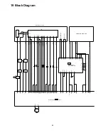
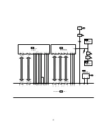
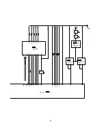


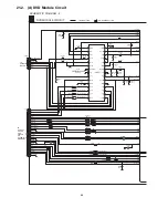
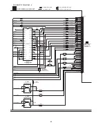


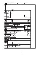
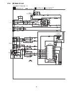


: MAIN SIGNAL LINE
: FM OSC SIGNAL LINE
: FM SIGNAL LINE
: CD SIGNAL LINE
: AM OSC SIGNAL LINE
: AUX SIGNAL LINE
: AM SIGNAL LINE
: FM/AM SIGNAL LINE
: CD-DA (AUDIO/VIDEO) SIGNAL LINE
: PLAYBACK SIGNAL LINE
: RECORD SIGNAL LINE
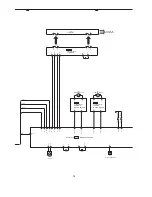
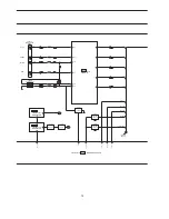
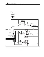
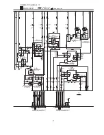
E5801
T9500
SYNC
HP _SW
JK6801
HEADPHONE
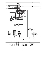
VOLTAGE
REGULATOR
(-VP)
Q9503
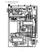
POWER TRANSFORMER
T9501
POWER
SWITCH
CONTROL
F1
Q9500
9V VOLTAGE
REGULATOR
15V VOLTAGE
REGULATOR
5V VOLTAGE
REGULATOR
CURRENT STABILISER/
LIMIT SWITCH/
10V VOLTAGE REGULATOR
Q2710
D9512,D9517
Q9501
SYSTEM 6V
VOLTAGE
REGULATOR
JK9500
AC INLET
FP9500
FP9501
FP5833
SUB
TRANSFORMER
D9522-D9529
Q5804, Q5806, Q5807
Q5808
Q5803
Q5809
B
SYNCHRONISING
SWITCH
Z9500
D9518-D9521
Q9502
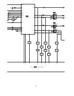
: DVD (VIDEO) SIGNAL LINE
: DVD (AUDIO) SIGNAL LINE
Q6805
SWITCH
Q6804
SWITCH
Q6803
SWITCH
HP _OUT
SYSTEM 6V
VOLTAGE
REGULATOR
SWITCH
Q5802, Q5805
RESET
Q2702
SWITCH
F2
FP9502
FP9503
B
B
B
B
RL9500
RCH
TO
FL DISPLAY
SIGNAL LINES
( ) Indicates the Pin No. of Right Channel.
NOTE : Signal Lines are applicable to the Left Channel only.
S5950
VOLTAGE
SELECTOR
F3
B
B
B
B
B
76
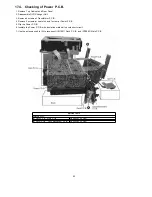
Summary of Contents for SA-TM900DVD
Page 9: ...10 Operation Procedures 9 ...
Page 10: ...10 ...
Page 11: ...11 Disc information 11 ...
Page 12: ...12 ...
Page 15: ...15 ...
Page 35: ...Step 2 Remove DVD traverse deck by rotating to the arrow direction 35 ...
Page 39: ...39 ...
Page 40: ...16 17 3 Replacement for the traverse deck Follow the Step 1 Step 10 of item 16 17 2 40 ...
Page 42: ...42 ...
Page 43: ...43 ...
Page 45: ...45 ...
Page 46: ...46 ...
Page 47: ...47 ...
Page 48: ...48 ...
Page 49: ...49 ...
Page 50: ...50 ...
Page 51: ...51 ...
Page 52: ...52 ...
Page 53: ...53 ...
Page 54: ...54 ...
Page 55: ...55 ...
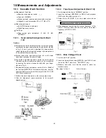
Page 65: ...18 3 1 Cassette Deck Section 18 3 2 Adjustment Point 18 3 Alignment Points 65 ...
Page 77: ...20 Voltage Measurement This section is not available at time of issue 77 ...
Page 107: ...35 6 6 7 7 7 7 7 7 6 U 2 2 2 0 2 1 2 2 1 2 2 1 2 1 2 2 2 4 6 35 ...
Page 109: ...0 7 7 7 2 2 2 3 4 6 EW ODEL GT IC OTE ATERIAL 3IZE MODIFIED 0 4 25 ...
Page 110: ...2 0 7 2 0 5NIT MM 0ARTS NO AME PPROVED HECKED 3 ...
Page 111: ......
Page 112: ......
Page 113: ......
Page 114: ......
Page 115: ......
Page 116: ...116 ...
Page 117: ...117 ...
Page 139: ...26 1 Deck Mechanism RAA3413 S 26 1 1 Deck Mechanism Parts Location 139 ...
Page 140: ...140 ...
Page 142: ...26 2 DVD Loading Mechanism 26 2 1 DVD Loading Mechanism Parts Location 142 ...
Page 143: ...143 ...
Page 145: ...26 3 Cabinet 26 3 1 Cabinet Parts Location 145 ...
Page 146: ...146 ...
Page 147: ...147 ...
Page 188: ...3 Connection of the Wiring Diagram 4 Cabinet Parts Location 5 service m speaker 11 ...
Page 192: ...3 Connection of the Wiring Diagram 9 service m speaker ...
Page 193: ...4 Cabinet Parts Location 3 10 service m speaker ...
Page 198: ...3 Connection of the Wiring Diagram 4 Cabinet Parts Location 15 service m speaker ...
Page 203: ...3 Connection of the Wiring Diagram 4 Cabinet Parts Location 20 service m speaker ...


