
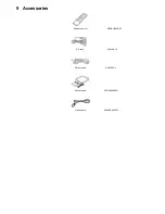


Item
Operational Condition
and Key Function
Details
Display
TO Exit Mode
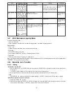
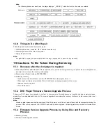
Measurement of CD
laser current electricity
While
the
player
is
stopped and no disc is
inserted, press and hold
down the
button
on the player and the
number button “3” on the
remote controller unit.
Press
“Dimmer/FL
Display” button for next
page
Measurement
of
CD laser
current
electricity
Measures CD laser current electricity
and displays the result together with
the
initialization
value
stored
in
EEPROM.
After
measurement,
CD
laser is lit till the power is turned off (or
goes off when the primary power is
turned off).
LDC
*1
xxx
*2
yyyy
*3
*1
: CD laser current electricity
measurement mode
*2
: Current electricity initialization
value stored in EEPROM
*3
: Present value of current
electricity
Values are shown in the decimal
digit. The above example indicates
the current electricity initialization
value is 28mA and its present
value is 26mA when laser is turned
on.
Automatically exits
the mode after five
seconds.
User initialization
While
the
player
is
stopped and no disc is
inserted, press and hold
down the
button
on the player and the
number button
on the remote controller
unit.
User initialization
The user setting recovers the factory
setting.
“INIT”
Automatically exits
the mode after five
seconds.
Region display
While
the
player
is
stopped and no disc is
inserted, press and hold
down the
button on
the
player
and
the
number button, “6” on
the
remote
controller
unit.
Region display
[2_P6_632]
s : Panecon model type
rrr : Panecon release number
x : Syscon generation (45)
y: Syscon model type
zzz: Syscon release number
Automatically exits
the mode after five
seconds.
Firmware
version
display
While
the
player
is
stopped and no disc is
inserted, press and hold
down the
button
on the player and the
number button, “7” on
the
remote
controller
unit.
Press
“Dimmer/FL
Display” button for next
page
Firmware version display
rrr
*1
xx
*2
y
*3
zzz
*4
*1
: Panel computer release number
*2
: System computer generation
*3
: System computer model type
*4
:
System
computer
release
number
Automatically exits
the mode after five
seconds.
Region and firmware
display
While
the
player
is
stopped and no disc is
inserted, press and hold
down the
button
on the player and the
number button, “8” on
the
remote
controller
unit.
Region and firmware version display
2
*1
90
*2
E3
*3
22
*4
*1
: Region number
*2
: System computer generation
*3
: System computer model type
*4
:
System
computer
release
number
Automatically exits
the mode after five
seconds.
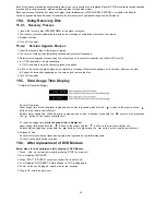
Laser use time
While
the
player
is
stopped and no disc is
inserted, press and hold
down the
button
on the player and the
button
on
the
remote controller unit.
Press
“Dimmer/FL
Display” button for next
page
Laser usage time
Measures each for DVD and CD
respectively.
T1_ _1234
The numbers in the left show
usage time for DVD laser and
those in the right for CD laser. The
four-digit number is shown by the
ten hours in the decimal digit. The
number after 0000 is 9999.
Automatically exits
the mode after five
seconds.
Reset laser use time
While the usage time 1 is
displayed,
press
and
hold
down
the
button on the player and
the
button on the
remote controller unit.
Laser usage time reset
Resets both for DVD and CD at once.
T1_ _0000
Automatically exits
the mode after five
seconds.
21
Summary of Contents for SA-TM900DVD
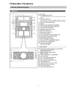
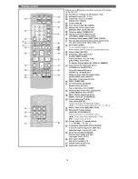
Page 9: ...10 Operation Procedures 9 ...
Page 10: ...10 ...
Page 11: ...11 Disc information 11 ...
Page 12: ...12 ...
Page 15: ...15 ...
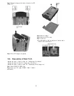
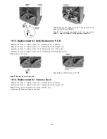
Page 35: ...Step 2 Remove DVD traverse deck by rotating to the arrow direction 35 ...
Page 39: ...39 ...
Page 40: ...16 17 3 Replacement for the traverse deck Follow the Step 1 Step 10 of item 16 17 2 40 ...
Page 42: ...42 ...
Page 43: ...43 ...
Page 45: ...45 ...
Page 46: ...46 ...
Page 47: ...47 ...
Page 48: ...48 ...
Page 49: ...49 ...
Page 50: ...50 ...
Page 51: ...51 ...
Page 52: ...52 ...
Page 53: ...53 ...
Page 54: ...54 ...
Page 55: ...55 ...
Page 65: ...18 3 1 Cassette Deck Section 18 3 2 Adjustment Point 18 3 Alignment Points 65 ...
Page 77: ...20 Voltage Measurement This section is not available at time of issue 77 ...
Page 107: ...35 6 6 7 7 7 7 7 7 6 U 2 2 2 0 2 1 2 2 1 2 2 1 2 1 2 2 2 4 6 35 ...
Page 109: ...0 7 7 7 2 2 2 3 4 6 EW ODEL GT IC OTE ATERIAL 3IZE MODIFIED 0 4 25 ...
Page 110: ...2 0 7 2 0 5NIT MM 0ARTS NO AME PPROVED HECKED 3 ...
Page 111: ......
Page 112: ......
Page 113: ......
Page 114: ......
Page 115: ......
Page 116: ...116 ...
Page 117: ...117 ...
Page 139: ...26 1 Deck Mechanism RAA3413 S 26 1 1 Deck Mechanism Parts Location 139 ...
Page 140: ...140 ...
Page 142: ...26 2 DVD Loading Mechanism 26 2 1 DVD Loading Mechanism Parts Location 142 ...
Page 143: ...143 ...
Page 145: ...26 3 Cabinet 26 3 1 Cabinet Parts Location 145 ...
Page 146: ...146 ...
Page 147: ...147 ...
Page 188: ...3 Connection of the Wiring Diagram 4 Cabinet Parts Location 5 service m speaker 11 ...
Page 192: ...3 Connection of the Wiring Diagram 9 service m speaker ...
Page 193: ...4 Cabinet Parts Location 3 10 service m speaker ...
Page 198: ...3 Connection of the Wiring Diagram 4 Cabinet Parts Location 15 service m speaker ...
Page 203: ...3 Connection of the Wiring Diagram 4 Cabinet Parts Location 20 service m speaker ...


