10.17. Disassembly of Regulator IC
(IC2903)
·
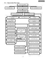
Follow (Step 1) to (Step 3) of Item 10.3.
·
Follow (Step 1) to (Step 3) of Item 10.4.
·
Follow (Step 1) to (Step 4) of Item 10.5.
·
Follow (Step 1) to (Step 4) of Item 10.7.
·
Follow (Step 1) to (Step 4) of Item 10.8.
·
Follow (Step 1) to (Step 7) of Item 10.16.
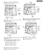
Step 1
Desolder pins of the regulator IC (IC2903) on the back
side of Main P.C.B.
Step 2
Remove 1 screw.
Step 3
Remove the regulator IC (IC2903) from the IC heatsink
extrussion.
Note :
Refer to the diagrams of Main P.C.B. (Item 10.16.) for
location of the part.
10.18. Disassembly of SMPS & AC-
Inlet P.C.B.
·
Follow (Step 1) to (Step 3) of Item 10.3.
·
Follow (Step 1) to (Step 3) of Item 10.4.
·
Follow (Step 1) to (Step 4) of Item 10.5.
·
Follow (Step 1) to (Step 4) of Item 10.7.
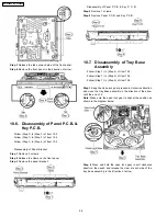
Step 1
Detach FFC cable from the connectors (CN5801 &
CN5802) on SMPS P.C.B.
Step 2
Release the lead clamper.
Step 3
Remove 2 screws from AC-Inlet P.C.B. & 4 screws from
SMPS P.C.B.
Step 4
Remove the P.C.B. bracket.
Step 5
Remove 1 screw from the rear panel.
Step 6
Release the tab in the direction of arrow.
62
SA-PT650P / SA-PT650PC
Summary of Contents for SA-PT650P
Page 12: ...12 SA PT650P SA PT650PC ...
Page 18: ...7 5 Using the Music Port 18 SA PT650P SA PT650PC ...
Page 54: ...10 2 Main Components and P C B Locations 54 SA PT650P SA PT650PC ...
Page 75: ...75 SA PT650P SA PT650PC ...
Page 90: ...SA PT650P SA PT650PC 90 ...
Page 98: ...SA PT650P SA PT650PC 98 ...
Page 100: ...100 SA PT650P SA PT650PC ...
Page 120: ...SA PT650P SA PT650PC 120 ...
Page 128: ...SA PT650P SA PT650PC 128 ...
Page 135: ...25 Exploded Views 135 SA PT650P SA PT650PC ...
Page 136: ...136 SA PT650P SA PT650PC ...
Page 137: ...25 1 Cabinet Parts Location SA PT650P SA PT650PC 137 ...
Page 138: ...SA PT650P SA PT650PC 138 ...


