


7.3. Error Code Table
7.3.1. Traverse Error Code Table
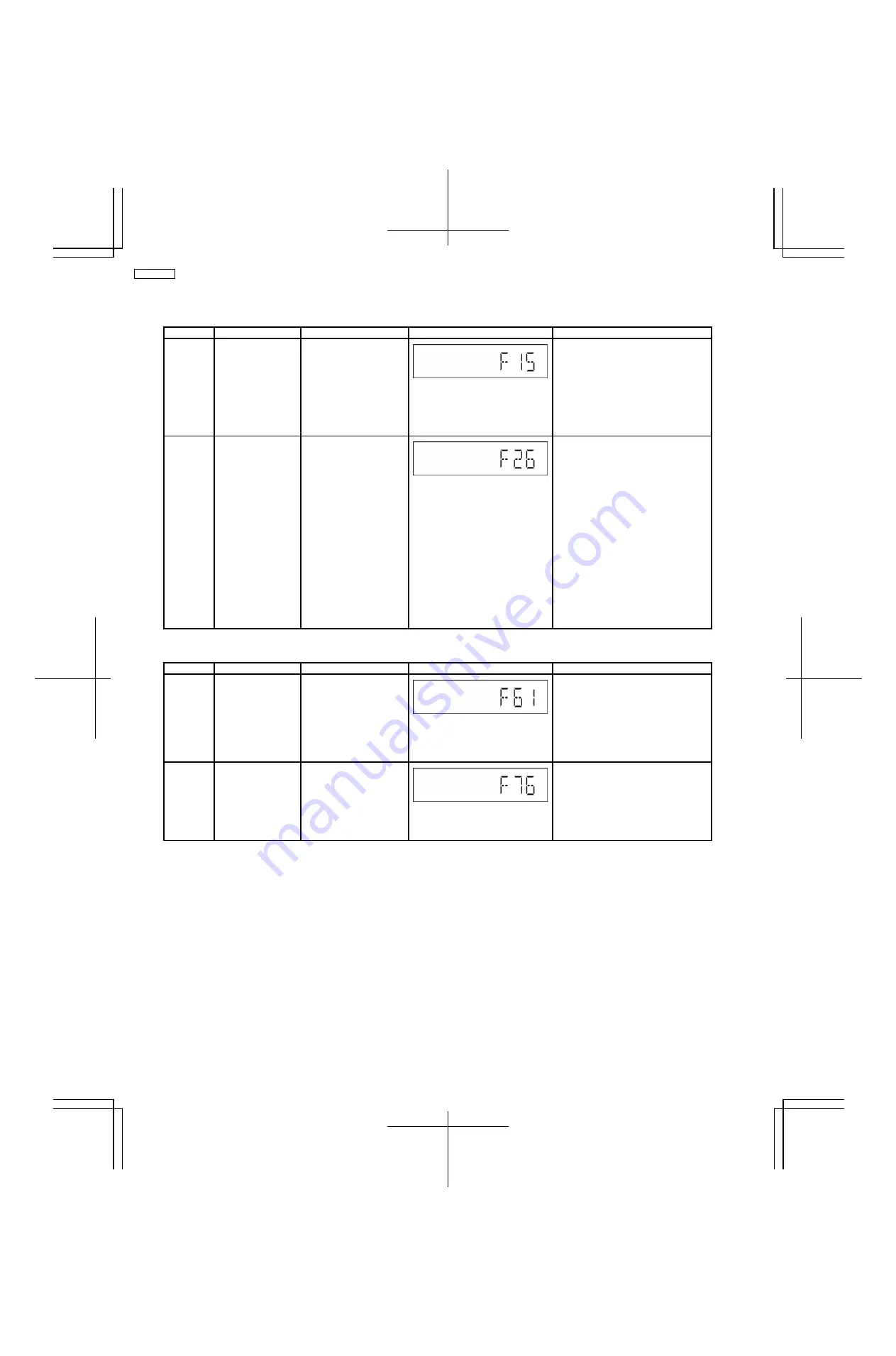
Error Code Diagnosis Contents Description of error
Automatic FL Display
Remarks
F15
CD REST SW
Abnormal
At initial setting of CD
traverse position, if the
RESET SW ON is not
detected even though the
fail safe timer time is over
(10 sec), it is memorized
as an error and the error
number can be cleared
only at the start up of
micro-p after reset.
Press [1] on remote control for next error.
CD F26
Communication
between CD servo
LSI and micro-p
abnormal.
1) At the time of switching
to CD function, SENSE =
H shall be detected using
DTMS system setting
command. If the error is
memorized when SENSE =
L is not detected within fail
safe timer time (20 mSec),
[F26] shall be displayed
simultaneously. This
display shall be retained if
the power is ON and at CD
function. If this error
occurs, CD operation
afterward shall not be
executed as in the case of
[NO DISC].
2) This error number can
be cleared only at the start
up of micro-p reset.
Press [1] on remote control for next
error.
7.3.2. Power Supply & Digital Amplifier Error Code Table
Error Code Diagnosis Contents Description of error
Automatic FL Display
Remarks
F61
The abnormalities in
an output or power
supply circuit of
POWER AMP
In normal operation, when
DCDET2 goes to “L” (Low)
(Not during POWER OFF
condition), F61 appears on
FL Display for 1 second and
PCONT goes to “L” (Low).
This
is due to speaker
output has DC voltage or
fan is not working.
Press [1] on remote control for next
error.
F76
Abnormality in the
output voltage of
stabilized power
supply.
In normal operation when
DCDET1 is detected “L”
(Low) for two consecutive
times, F76 is displayed on
FL for 1 second and after
that PCONT will be turned
to “L” (Low). This is due to
any of the DC voltages.
Press [1] on main unit for next error.
16
SA-PMX3GN
Summary of Contents for SA-PMX3GN
Page 10: ...6 Operation Procedures 6 1 Main Unit Key Buttons Operation 10 SA PMX3GN ...
Page 11: ...6 2 Remote Control Key Buttons Operation 6 3 Disc Information 11 SA PMX3GN ...
Page 18: ...18 SA PMX3GN ...
Page 20: ...8 2 Main Parts Location Diagram 20 SA PMX3GN ...
Page 56: ...56 SA PMX3GN ...
Page 58: ...SA PMX3GN 58 ...
Page 64: ...SA PMX3GN 64 ...
Page 66: ...66 SA PMX3GN ...
Page 86: ...SA PMX3GN 86 ...
Page 91: ...20 Exploded Views 20 1 Cabinet Parts Location SA PMX3GN 91 ...
Page 92: ...20 2 Packaging SA PMX3GN 92 ...


