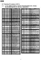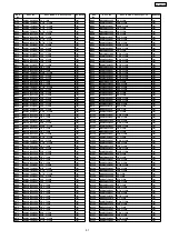
Pin No.
Mark
I/O
Function
1
IN2
I
Motor Driver 92 Input
2
PC2
I
Turntable Motor Drive Signal
(“L”:ON)
3
IN1
I
Motor Drive (1) Input
4
PC1
-
Traverse Motor Drive Signal (“L”:
ON)
5-8
N.C.
-
No Connection
9
PGND1
-
Ground Connection (1) for Drive
10
PVCC1
I
Power Supply (1) for Drive
11
D1-
O Motor Drive (1) reverse - action
output
12
D1+
O Motor Drive (1) forward - action
output
13
D2-
O Motor Drive (2) reverse - action
output
14
D2+
O Motor Drive (2) forward - action
output
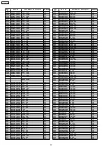
Pin No.
Mark
I/O
Function
1
VREF-
-
A/D Converter Reference GND
2
KEY 1
I
Key 1 Input
3
KEY 2
I
Key 2 Input
4
AN6 (MK_IN1)
I
Mech Condition Input1 (Mode
and TPS)
5
AN7 (MK_IN2)
I
Mech Condition Input2 (Half and
RECINF)
6
PWRDET
I
Power Detect
7
REGION
I
Destination Setting
8
VOL_DET1
I
Volume Lever Left
9
VOL_DET2
I
Volume Lever Right
10
VREF +
-
A/D Converter Reference Volt
11
VDD
-
Power Input Pin
12
OSC2 (8MHZ)
O
Main Oscillator Output
13
OSC1 (8MHZ)
I
Main Oscillator Input
14
VSS
-
GND
15
XI (32KHZ)
I
Suboscillator Input
16
XO (32KHZ)
O
Suboscillator Output
17
MMOD (GND)
-
Memory Mode Selection
18
N.C.
-
No Connection
19
RDS_DATA
I/O
RDS IC CTRL
20
RDS_CLK
O
RDS CLK IN
21
CD_MDATA
O
CD LSI Command Data
22
CD_STAT
I
CD Status Input
23
CD_MCLK
O
CD LSI Command Clock
24
N.C.
-
No Connection
25
PCONT1
O
Power Control Output1 (PWR
SPLY, Active High)
26
RMT
I
Remocon Input
27
HALT
I
AC Failure Detect Signal
28
CD_OPEN
_SW
I
CD Open Switch (L: Open, H:
Close)
29
REST_SW
I
CD Tranverse Limit SW
30
BLKCK
I
CD Subcode Block Clock Input
31
N.C.
-
No Connection
32
N.C.
-
No Connection
33
NRST
I
Micom Reset (L: Reset)
34
N.C.
-
No Connection
35
CD_RST
O
CD Reset Output
36
CD_MLD
O
CD LSI Command Load
37
N.C.
-
No Connection
38
N.C.
-
No Connection
39
N.C.
-
No Connection
40
FL_CS
O
FL Strobe Output
41
N.C.
-
No Connection
42
FL_DATA
O
FL Data Output
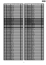
Pin No.
Mark
I/O
Function
15
D3-
O Motor Drive (3) reverse - action
output
16
D3+
O Motor Drive (3) forward - action
output
17
D4-
O Motor Drive (4) reverse - action
output
18
D4+
O Motor Drive (4) forward - action
output
19
PVCC2
-
Power Supply (2) for Driver
20
PGND2
-
Ground Connection (2) for Driver
21-24
N.C.
O No Connection
25
VCC
I
Power Supply terminal
26
VREF
I
Reference Voltage Input
27
IN4
I
Motor Driver (4) Input
28
IN3
I
Motor Driver (3) Input
Pin No.
Mark
I/O
Function
43
N.C.
-
No Connection
44
FL_CLK
O
FL Clock Output
45
SDA
I/O
IIC Data Line For Tuner
46
N.C.
-
No Connection
47
CL
O
IIC Clock Signal For Tuner
48
N.C.
-
No Connection
49
PCONT2
O
Power Control Output2 (PWR
AMP, active H)
50
DEMO
I
Demo Mode Setting (H: OFF, L:
ON)
51
N.C.
-
No Connection
52
HP_SW
-
No Connection
53
MUTE A
O
Audio Mute O/P (L: Mute On)
54
N.C.
-
No Connection
55
N.C.
-
No Connection
56
ASP_CLK
O
ASP CLK
57
ASP_DAT
O
ASP Data
58
N.C.
-
No Connection
59
N.C.
-
No Connection
60
N.C.
-
No Connection
61
E_DATA
I/O
Eeprom Data In/Out
62
E_CLK
O
Eeprom Clock Output
63
E_CS
O
Eeprom CS Output
64
N.C.
-
No Connection
65
TUNED
I/O
Tuner Tuned Signal
66
STEREO
I/O
Tuner Stereo Signal
67
N.C.
-
No Connection
68
N.C.
-
No Connection
69
N.C.
-
No Connection
70
MOTOR_H
O
Deck Motor Control Out (H: ON)
71
PL_H
O
Deck Plunger Control Out (H:
On)
72
N.C.
-
No Connection
73
N.C.
-
No Connection
74
TAPE_EJECT
O
Tape Eject SW I/P (L: SW On)
75
PHOTO
I
Deck Photo SW Input
76
REC_H
O
Deck Rec Control Output
(Active High)
77
N.C.
-
No Connection
78
DMT
O
Deck Mute Output (L: Mute On)
79
WMA
I
Model Select (L)
80
N.C.
-
No Connection
81
N.C.
-
No Connection
82
N.C.
-
No Connection
83
N.C.
-
No Connection
84
N.C.
-
No Connection
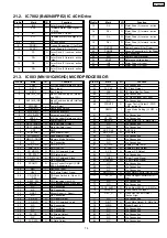
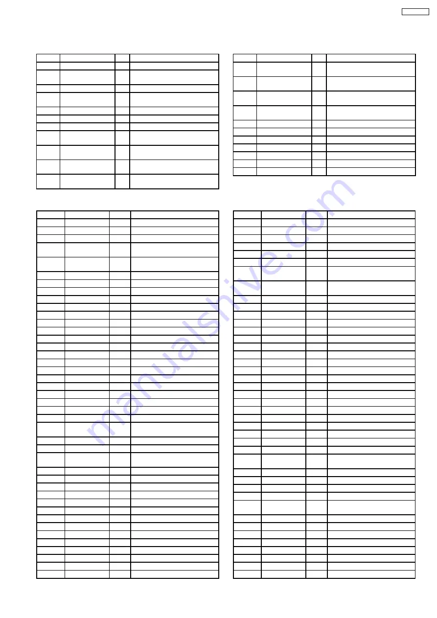
21.2. IC7002 (BA5948FPE2) IC 4CH Drive
21.3. IC803 (MN101C49GHD) MICROPROCESSOR
79
SA-PM33EE
Summary of Contents for SA-PM33EE
Page 11: ...7 Operating Instructions Procedures 7 1 Main Unit Remote Control Operation 11 SA PM33EE ...
Page 12: ...7 2 Disc Information 12 SA PM33EE ...
Page 21: ...9 3 Main Parts Location Diagram 21 SA PM33EE ...
Page 30: ...30 SA PM33EE ...
Page 31: ...31 SA PM33EE ...
Page 35: ...35 SA PM33EE ...
Page 38: ...11 2 Checking and Repairing of Panel P C B 38 SA PM33EE ...
Page 39: ...11 3 Checking and Repairing of Tuner Pack P C B 39 SA PM33EE ...
Page 40: ...11 4 Checking and Repairing of Transformer P C B 40 SA PM33EE ...
Page 41: ...11 5 Checking and Repairing of Main P C B 41 SA PM33EE ...
Page 42: ...11 6 Checking and Repairing of CD Mechanism P C B 42 SA PM33EE ...
Page 43: ...11 7 Checking and Repairing of Speaker Terminal P C B 43 SA PM33EE ...
Page 44: ...11 8 Checking and Repairing of Power P C B 44 SA PM33EE ...
Page 46: ...Fig 7 46 SA PM33EE ...
Page 56: ...SA PM33EE 56 ...
Page 60: ...SA PM33EE 60 ...
Page 62: ...62 SA PM33EE ...
Page 70: ...SA PM33EE 70 ...
Page 81: ...22 Troubleshooting Flowchart CD Section Circuit 81 SA PM33EE ...
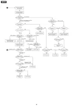
Page 82: ...82 SA PM33EE ...
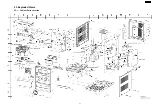
Page 83: ...23 Exploded Views 23 1 Cabinet Parts Location SA PM33EE 83 ...
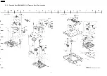
Page 84: ...23 2 Cassette Deck RAA4402 1S Traverse Deck Part Location SA PM33EE 84 ...
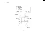
Page 85: ...23 3 Packaging SA PM33EE 85 ...
Page 86: ...SA PM33EE 86 ...


