13 Caution for Replacing Parts
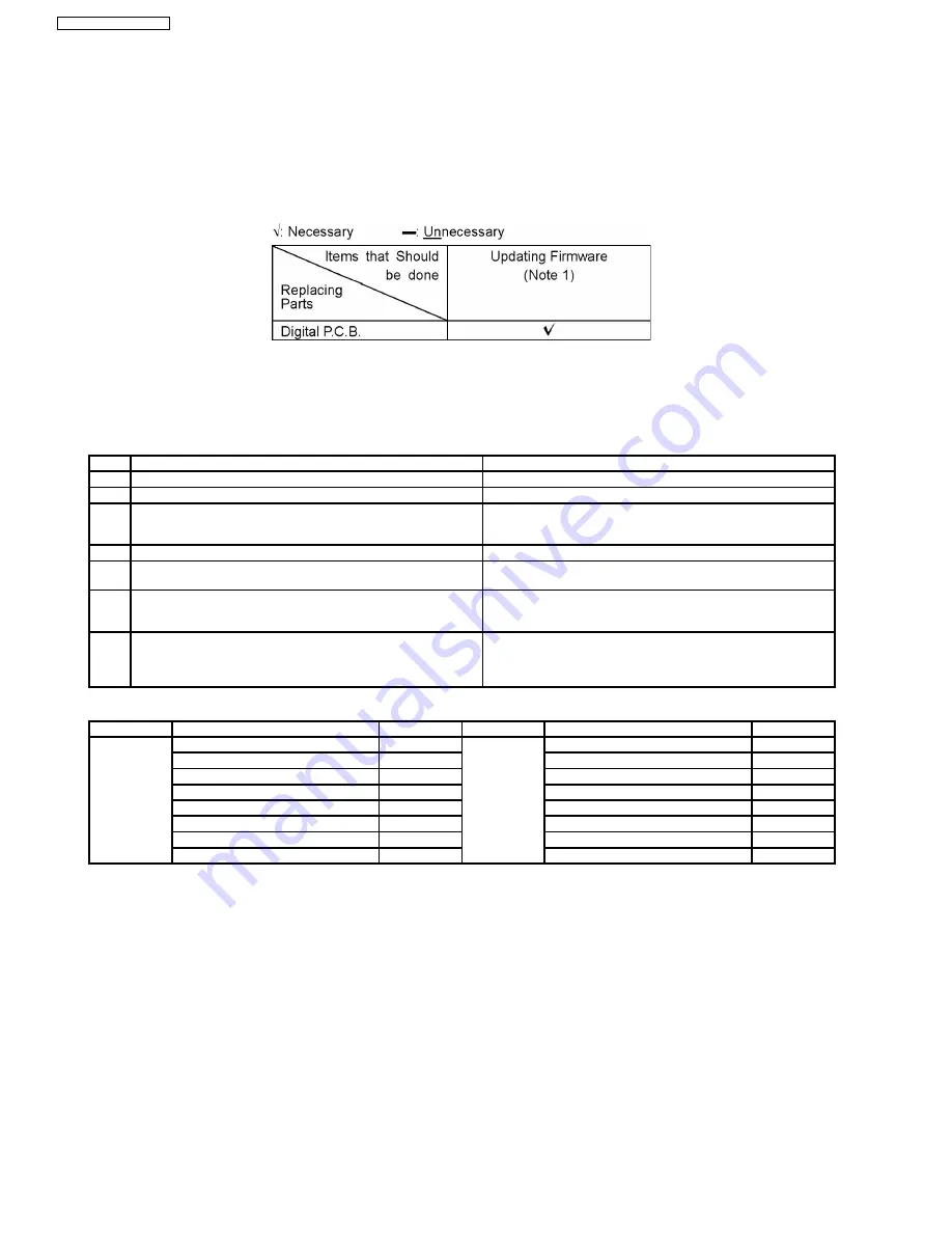
13.1. Notice after replacing Digital P.C.B.
After replacing Digital P.C.B., Test is displayed on FL.
Once power off, and start-up again.
13.2. Items that should be done after replacing parts
Note1:
Download latest Firmware and burn it on CD-R or CD-RW, and update Firmware.
13.3. Standard Inspection Specifications after Making Repairs
After making repairs, we recommend performing the following inspection, to check normal operation.
No.
Procedure
Item to Check
1
Turn on the power, and confirm items pointed out.
Items pointed out should reappear.
2
Insert RAM disc.
The Panasonic RAM disc should be recognized.
4
Perform playback for one minute using the RAM disc.
No abnormality should be seen in the picture, sound or operation.
*Panasonic DVD-RAM disc should be used when recording and
playback.
5
Perform playback for one minute using the BD-Video disc.
No abnormality should be seen in the picture, sound or operation.
6
If a problem is caused by a BD-Video disc, VCD, DVD-R, DVD-
Video, Audio-CD, or MP3, playback the test disc.
No abnormality should be seen in the picture, sound or operation.
7
After checking and making repairs, upgrade the firmware to the
latest version.
Make sure that [UPD OK] appear in the FL Displays.
*[UNSUPPORT] display means the unit is already updated to
newest same version. Then version up is not necessary.
8
Transfer [9][9] in the service mode setting, and initialize the
service setting (return various settings and error information to
their default values. The laser time is not included in this
initialization).
Make sure that [CLR] appears in the FL display.
After checking it, turn the power off.
Use the following checklist to establish the judgment creteria for the picture and sound.
Item
Contents
Check
Item
Contents
Check
Picture
Block Noise
Sound
Distorted sound
Crosscut noise
Noise (static, background noise, etc.)
Dot noise
The sound level is too low
Picture disruption
The sound level is too high
Not bright enough
The sound level change
Too bright
Flickering color
Color fading
68
SA-BT100P / SA-BT100PC
Summary of Contents for SA-BT100P
Page 40: ...40 SA BT100P SA BT100PC ...
Page 42: ...10 2 Main Components and P C B Locations 42 SA BT100P SA BT100PC ...
Page 80: ...SA BT100P SA BT100PC 80 ...
Page 94: ...SA BT100P SA BT100PC 94 ...
Page 96: ...96 SA BT100P SA BT100PC ...
Page 132: ...SA BT100P SA BT100PC 132 ...
Page 140: ...SA BT100P SA BT100PC 140 ...
Page 144: ...CN5501 Fig 3 Fan Connector 144 SA BT100P SA BT100PC ...
Page 148: ...148 SA BT100P SA BT100PC ...
Page 149: ...23 Exploded Views 23 1 Cabinet Parts Location SA BT100P SA BT100PC 149 ...
Page 150: ...SA BT100P SA BT100PC 150 ...
Page 151: ...23 2 Packaging SA BT100P SA BT100PC 151 ...
Page 152: ...SA BT100P SA BT100PC 152 ...


