


77
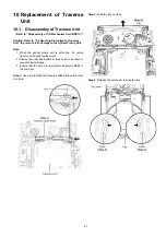
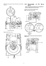
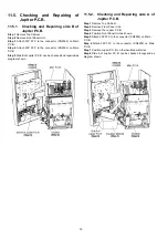
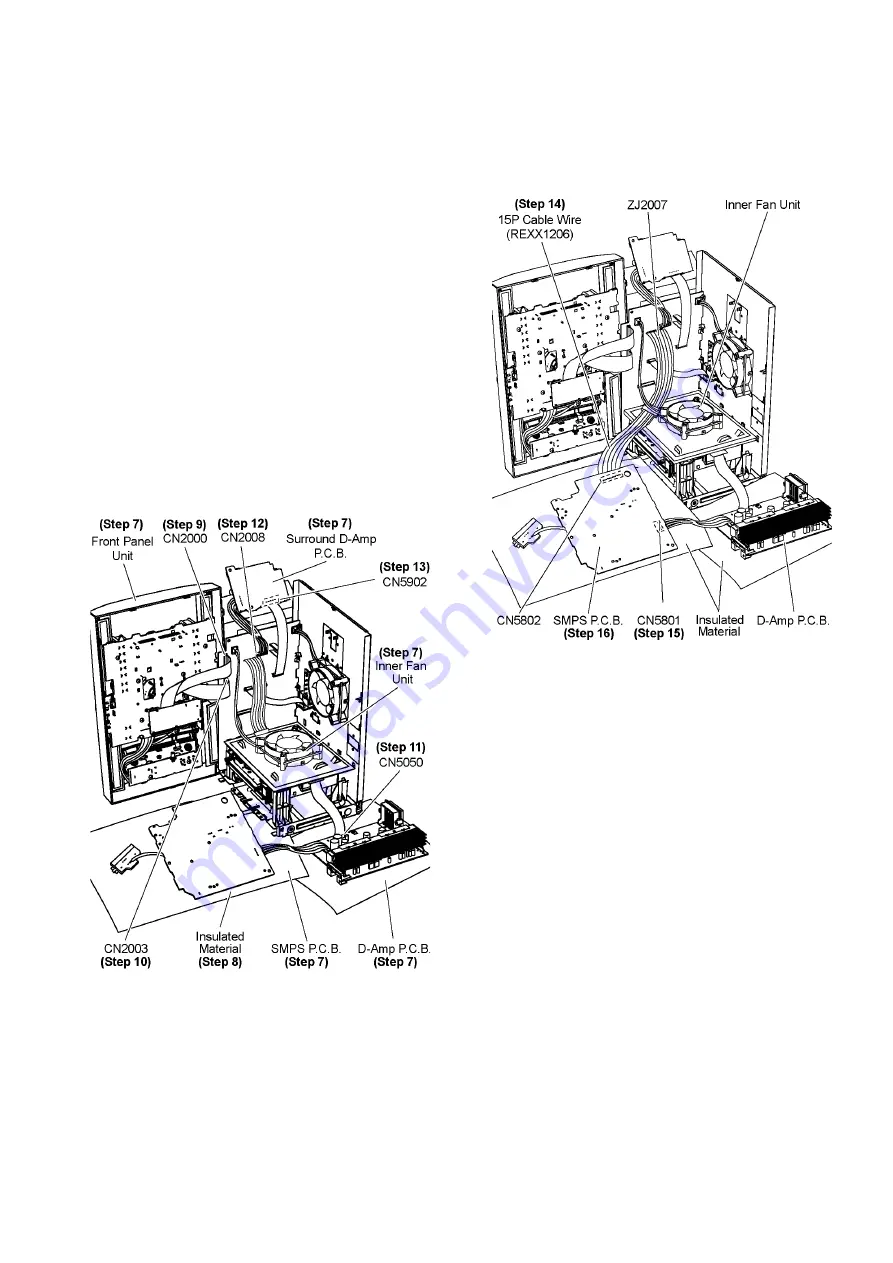
11.6. Checking and Repairing of
SMPS P.C.B.
Step 1 Remove Top Cabinet.
Step 2 Remove Front Panel Unit.
Step 3 Remove D-Amp P.C.B..
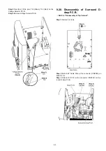
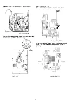
Step 4 Remove Surround D-Amp P.C.B..
Step 5 Remove Inner Fan Unit.
Step 6 Remove SMPS P.C.B..
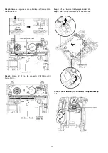
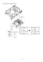
Step 7 Position Front Panel Unit, Surround D-Amp P.C.B.,
Inner Fan Unit, SMPS P.C.B. & D-Amp P.C.B. as diagram
shown.
Step 8 Position SMPS P.C.B., Surround D-Amp P.C.B., D-Amp
P.C.B. on the insulated material.
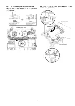
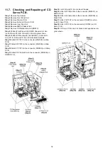
Step 9 Attach 30P FFC to the connector (CN2000) on Main
P.C.B..
Step 10 Attach 30P FFC to the connector (CN2003) on Main
P.C.B..
Step 11 Attach 17P FFC to the connector (CN5050) on D-Amp
P.C.B..
Step 12 Attach 6P Cable Wire to the connector (CN2008) on
Main P.C.B..
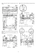
Step 13 Attach 12P FFC to the connector (CN5902) on Sur-
round D-Amp P.C.B..
Step 14 Extend the Cable Wire with extension Cable Wire
(REXX1206) (15P Cable Wire from ZJ2007 to CN5802).
Step 15 Connect 6P Cable Wire to the connector (CN5801) on
SMPS P.C.B..
Step 16 SMPS P.C.B. can be checked & repaired as diagram
shown.
Summary of Contents for SA-AKX92PH
Page 13: ...13 5 Location of Controls and Components 5 1 Main Unit Key Button Operation ...
Page 14: ...14 5 2 Remote Control Key Button Operation ...
Page 15: ...15 5 3 Media Information ...
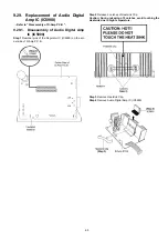
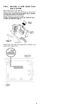
Page 27: ...27 7 2 4 Surround D Amp P C B Fig 4 Surround D Amp P C B Audio Digital Amp IC IC5900 ...
Page 33: ...33 9 2 Main Components and P C B Locations ...
Page 73: ...73 Step 9 Ground the 24P FFC with a short pin ...
Page 92: ...92 ...
Page 93: ...93 14 Simplified Block Diagram 14 1 Overall Simplified Block Diagram ...
Page 104: ...104 ...
Page 140: ...140 ...
Page 157: ...157 MMH1103 ...


