50
1
1
2
3
4
5
6
7
8
9
A
B
C
D
E
F
G
H
10
1
12
13
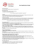
SA-AKX18PH/PN
MAIN P.C.B.
NOTE: " * " REF IS FOR INDICATION ONLY
A
MAIN P.C.B. (REP5061B...PH)
(REP5061A...PN)
(SIDE B)
PbF
C6023
C6048
IC6000
C6032
C6031
C6036
C6039
C6024
C6028
C6030
C6025
R6007
C6020
C6022
R6046
C6018
C6019
R6050
C6021
R6011
L6000
L6005
L6001
L6002
C6033
C6005
JK6000
R6300
R6301 C6069
R6069
R6068
R6302
R6303
C6070
R6304
R6305
C6071
R6307
C6074
R6306
R6058
C6061
R6060
C6062
R6062
C6064
R6066
R6067
C1008
C1009
R1004
R1005
R1006
DZ1000
C1013
R1008
C1015
R1016
C1019
IC1003
C1020
C1030
C1016
C1001
C1000
IC1000
IC1004
C1024
C1025
C1032
IC2004
C2172
C2180
C2178
LB2013
C2170
C2171 LB2012
C2173
R2158
P2004
P2005
(TO OPTICAL PICKUP UNIT)
R2162
R2160
R2161
R2159
R2163
R2164
R2165
R2166
R2156
R2157
R2173
R2172
R2174
R2175
R2176
R2177
R2178
R2179
R2180
R2181
C2166
C2167
R2185
R2186
R2095
R2096
R2097
R2182
R2183
R2184
R2154
R2153
C2168
C2169
LB2010
C2162
C2163
R2155
LB2011
D2002
C2165
C2164
Q2001
R2167
R2168
R2169
C2182
C2179
R2171
R2170
C2181
LB2014
C2183
R2086
R2067
R2057
IC2001
C2120
C2114
C2115
R2012
C2113
C2116
C2117
R2192
C2112
C2119
LB2005
R2001
Q2002
R2002
C2118
R2013
R2014
C2137
C2135
C2134
C2133
C2138
C2136
C2110
R2049
R2187
R2188
R2189
R2050
R2048
LB2002
C2125
R2076
R2068
R2069
R2070
R2071
C2108
C2107
C2147 R2055
R2103
R2104
R2105
R2107
R2027
R2028
R2029
R2051
R2052
C2132
R2039
R2053
R2054
X2001
R2036
R2035
C2129
C2128
C2131
X2002
R2037
R2038
C2130
R2074
R2075
R2201
R2202
R2018
R2020
R2019
R2016
R2017
R2015
R2100
R2102
R2024
R2033
C2111
C2124
LB2007
LB2004
C2123
R2311
R2034
R2023
R2022
C2104
C2105
R2021
R2072
R2110
R2073
R2111
R2496
R2222
R2099
C2127
LB2003
P2002
(FOR DEBUG)
IC2003
C2121
C2122
LB2006
C2126
LB2015
R2114
C2184
R2118
R2121
R2123
R2127
R2129
R2131
R2135
R2139
D2001
R2093
C2148
QR2002
R2338
R2339
R2340
R2330
R2089
R2420
R2423
R2421
R2419
CN2500
R1007
C1022
C1002
R1031
C1018
R1044
C1021
C1031
L1002
R1027
R1026
C1004
L1001
D1000
R1030
C1003
IC1002
C1005
C6109
R2063
R2422
R2065
D1006
D1007
C6108
R60
R56
C61
C62
C67
IC52
JK51
JK52
LB52
L52
L53
R51
R52
R53
R54
R55
R57
R59
VA51
JK6002
R6146
C6099
R6147
C6100
R6134
R6136
R6135
R6133
C66
C52
LB51
C51
L51
L6006
Q6001
Q6002
R6054
R6055
R6056
R6057
C6027
R6070
R6132
C6068
Q6007
Q6300
C6500
C6521
C6592
C6591
R6559
LB6501
R6542
R6541
R6532
R6531
R6511
R6512
R6521
R6522
C6501
C6523
C6502
C6525
C6561
C6560
X6500
R6502
R6501
C6529
R6506
R6505
R6504
R6503
C6528
LB6500
R6553
R6552
R6551
R6550
C6527
R6557
R6556
R6554
C6551
C6550
IC6500
R2117
R2115
R2119
C2144
IC2002
IC2005
R2026
C2141
C2140
QR2500
R2504
R2510
Q2500
R2503
C2508
IC2501
C2504
LB2503
C2507
IC2502
C2506
L1000
R6594
R2498
LB2016
R2507
C2505
IC2500
R2501
CN2502
HEATSINK
ZA6000*
R2149
R2150
R2151
R2152
IC7000*
(BLUETOOTH MODULE)
R6587
R6582
R6581
R2106
R2108
R6072
C6047
C6045
C7000
L7000
R2006
C2006
C2007
R1025
D1002
D1001
C1023
Q1000
D1005
C1033
R1038
R1033
R2004
R2005
C2004
C2005
C6046
C1044
IC1005
LB53
C1045
R2499
R1064
R1066
R2514
R1067
IC7001
C7001
C7002
R7001
R1069
C1049
R1070
R1068
C1046
C1048
C1047
C2536
C2537
C2535
C2534
C2533
C2532
C2530
C2528
C2526
C2524
C2522
C2531
C2529
C2527
C2523
C2521
LB2024
LB54
LB55
ZJ1002*
(TO SMPS MODULE P.C.B.)
FM ANT
AM ANT
AUX IN
TO SPEAKERS
3760A
3760A
R6061 C6063
R2417
D1008
R2312...AKX18
R2314...PN
R2315...PH
R2520
1-R+
2-R-
3-L+
4-L-
44
40
35
30
25
23
22
20
15
10
5
1
1
5
6
10
3
2
1
1
2
3 4
28 272625242322
21201918171615
14
13
12
11
10
9
8
7
6
5
4
3
2
1
30
29
1
3
7
5
2
4
6
8
10
9
24
23
22
21
20
19
18
17
16
15
14
13
12
11
10
9
8
7
6
5
4
3
2
1
1
5
10
15
20
25
30
32
33
35
40
45
50
55
60
64
65
70
75
80
85
90
95
96
97 100 105 110 115 120 125 128
4
3
2
1
1
2
3
4
5
6
7
8
1
2
3
4
5 6 7 8
1
2
3
4
5
6
7
8
9
11
10
13
12
15
14
17
16
1
5
6
10
2
1
1
20
16
15
11
10
6 5
1
6
4
3
1
3
2
1
4
4
3 2
1
48 45
40 37
36
35
30
25
24
20
15
13
12
10
5
1
1
2
3
4
5
6
7
8
1
2
3 4
5
4
1
2
3
5
4
1
2
3
10 8
5
3
2
1
6
7
1
2
3
4
5
6
7
8
9
10
11
12
13
14
15
16
8
7
6
5
4
3
2
1
3
2
1
1
2
3
4
1
2
3
4
5
6
7
8
9
10
B
C
E
B
C
E
B
C
E
B
C
E
B
C
E
B
C
E
B
C
E
B
C
E
B
C
E
B
C
E
A
C
CA
Summary of Contents for SA-AKX18PH
Page 22: ...22 8 3 Main Components and P C B Locations ...
Page 30: ...30 ...
Page 36: ...36 ...
Page 38: ...38 ...
Page 52: ...52 ...
Page 60: ...60 ...
Page 68: ...68 MMH1401 ...