9 Self diagnosis and special mode setting
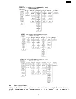
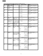
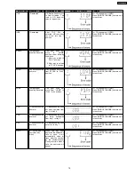
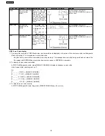
This unit is equipped with functions for checking and inspecting namely: Self-Diagnostic and Test Mode.
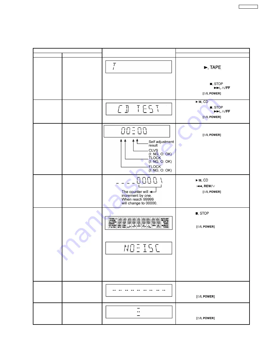
9.1. Special Mode Table
Item
FL Display
Key Operation
Mode Name
Description
Front Key
Self -Diagnostic
Mode
To
enter
into
self
diagnostic checking for
main unit.
1.
Select [
] for TAPE mode (Ensure no tape is
inserted).
2.
Press and hold [
]button for 3
seconds follow by [
].
To exit, press
button on
main unit or remote control.
CD Test Mode
To enter into checking the
reliability of changer unit.
1.
Select [
] for CD mode.
2.
Press and hold [
] button for 3
seconds follow by [
].
To exit, press
button on
main unit or remote control.
CD Auto
Adjustment
To check the CD auto
adjustment
result
for
FLOCK,
TLOCK
and
CLVS.
In CD Test Mode:
1.
Press [0] button on the remote control.
To exit, press
button on
main unit or remote control.
CD Changer
Reliability Test
(CRS1)
To
determine
the
reliability of CD Changer
Unit.
(For more
information,
refer to section 9.1.1)
In Self-Diagnostic Mode:
1.
Select [
] for CD mode.
2.
Press [
] button.
To exit, press
button on
main unit or remote control.
(The tray will return to PLAY position and then
power off)
Doctor Mode
To enter into Doctor
Mode for checking of
various items and
displaying EEPROM and
firmware version.
1.
2.
1.
All segments will light up for 1 second.
2.
The Check Sum of EEPROM and firmware
version will be display.
* ROM correction
** Firmware version No:
In any mode:
1.
Press [
] button on main unit
follow by [4] and [7] on remote control.
To exit, press [ENTER] button on remote
control or
button on main
unit or remote control.
Cold Start
To activate cold start
upon next AC power up.
In doctor mode:
1.
Press [4] button on remote control.
To exit, press [ENTER] button on remote
control or
button on main
unit or remote control.
Changer
Reliability Test
To check the function
operation of changer unit.
(For more
information,
refer to 9.1.1)
In doctor mode:
1.
Press [DISC] on remote control.
To exit, press [ENTER] button on remote
control or
button on main
unit or remote control.
15
SA-AK240GCP
Summary of Contents for SA-AK240GCP
Page 13: ...8 Operating Instructions Procedures 13 SA AK240GCP ...
Page 14: ...14 SA AK240GCP ...
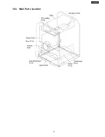
Page 23: ...10 3 Main Parts Location 23 SA AK240GCP ...
Page 40: ...12 2 Checking and Repairing of Transformer P C B 40 SA AK240GCP ...
Page 41: ...12 3 Checking and Repairing of Panel Deck Deck Mechanism P C B 41 SA AK240GCP ...
Page 42: ...12 4 Checking and Repairing of Power P C B 42 SA AK240GCP ...
Page 47: ...47 SA AK240GCP ...
Page 48: ...14 2 Power P C B Transformer P C B 48 SA AK240GCP ...
Page 49: ...14 3 Waveform Chart 49 SA AK240GCP ...
Page 50: ...50 SA AK240GCP ...
Page 52: ...52 SA AK240GCP ...
Page 58: ...58 SA AK240GCP ...
Page 60: ...SA AK240GCP 60 ...
Page 62: ...SA AK240GCP 62 ...
Page 68: ...SA AK240GCP 68 ...
Page 70: ...SA AK240GCP 70 ...
Page 74: ...SA AK240GCP 74 ...
Page 82: ...SA AK240GCP 82 ...
Page 87: ...21 Exploded Views 21 1 Cabinet Parts Location SA AK240GCP 87 ...
Page 88: ...SA AK240GCP 88 ...
Page 89: ...21 2 Deck Mechanism Parts Location RAA4502 S SA AK240GCP 89 ...
Page 90: ...21 3 Packaging SA AK240GCP 90 ...


