


19
Cautions During Brazing
●
Replace air inside the tube with nitrogen gas to prevent copper oxide fi lm from forming during the brazing process.
(Oxygen, carbon dioxide and Freon are not acceptable.)
●
Do not allow the tubing to get too hot during brazing. The nitrogen gas inside the tubing may overheat, causing
refrigerant system valves to become damaged. Therefore allow the tubing to cool when brazing.
●
Use a reducing valve for the nitrogen cylinder.
●
Do not use agents intended to prevent the formation of oxide fi lm. These agents adversely affect the refrigerant and
refrigerant oil, and may cause damage or malfunctions.
5-2. Connecting Tubing Between Indoor and Outdoor Units
(1) Tightly connect the indoor-side refrigerant tubing extended from
the wall with the outdoor-side tubing.
Indoor Unit Tubing Connection (
1
,
2
...
n-1
)
Indoor unit type
18
24
Gas tubing
inch
ø1/2
ø5/8
mm
ø12.7
ø15.88
Liquid tubing
inch
ø1/4
ø3/8
mm
ø6.35
ø9.52
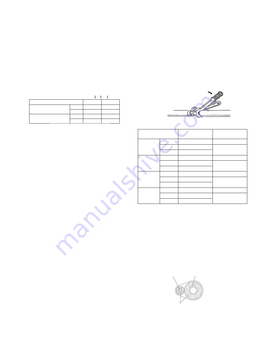
(2) To fasten the flare nuts, apply specified torque as at right:
Outdoor unit
Torque wrench
Spanner
Indoor unit
Fig. 5-6
●
When removing the fl are nuts from the tubing connections, or
when tightening them after connecting the tubing, be sure to
use a torque wrench and a spanner. (Fig. 5-6)
If the fl are nuts are over-tightened, the fl are may be
damaged, which could result in refrigerant leakage and
cause injury or asphyxiation to room occupants.
●
For the fl are nuts at tubing connections, be sure to use the
fl are nuts that were supplied with the unit, or else fl are nuts
for R410A (type 2). The refrigerant tubing that is used must
be of the correct wall thickness as shown in the table at right.
Because the pressure is approximately 1.6 times higher than
conventional refrigerant pressure, the use of ordinary fl are
nuts (type 1) or thin-walled tubes may result in tube rupture,
injury, or asphyxiation caused by refrigerant leakage.
Tube diameter
Tightening torque
approximate
Tube thickness
ø1/4"
(ø6.35 mm)
lbf·inch
120 – 160 lbf·inch
1/32”
N·m
14 – 18 N·m
0.8 mm
{k
g
f·cm}
{140 – 180 k
g
f·cm}
ø3/8”
(ø9.52 mm)
lbf·inch
300 – 360 lbf·inch
1/32”
N·m
34 – 42 N·m
0.8 mm
{k
g
f·cm}
{340 – 420 k
g
f·cm}
ø1/2”
(ø12.7 mm)
lbf·inch
430 – 540 lbf·inch
1/32”
N·m
49 – 61 N·m
0.8 mm
{k
g
f·cm}
{490 – 610 k
g
f·cm}
ø5/8”
(ø15.88
mm)
lbf·inch
590 – 710 lbf·inch
5/128”
N·m
68 – 82 N·m
1.0 mm
{k
g
f·cm}
{680 – 820 k
g
f·cm}
●
In order to prevent damage to the fl are caused by over-tightening of the fl are nuts, use the table above as a guide when
tightening.
●
When tightening the fl are nut on the liquid tube, use an adjustable wrench with a nominal handle length of 7-7/8 in. (200 mm).
5-3. Insulating the Refrigerant Tubing
Tubing Insulation
●
Thermal insulation must be applied to all units tubing,
including distribution joint (fi eld supply).
* For gas tubing, the insulation material must be heat
resistant to 248°F (120°C) or above. For other tubing, it
must be heat resistant to 176°F (80°C) or above.
Insulation material thickness must be 13/32” (10 mm) or
greater.
If the conditions inside the ceiling exceed DB 86°F (30°C)
and RH 70%, increase the thickness of the gas tubing
insulation material with one grade higher.
Liquid tubing
Gas tubing
Insulation
Two tubes arranged together
Fig. 5-7
00̲271654̲Eng.indb 19
00̲271654̲Eng.indb 19
2015/09/04 11:57:37
2015/09/04 11:57:37
Summary of Contents for S-18MK2U6
Page 26: ...26 NOTE ...
Page 27: ...27 NOTE ...


