background image

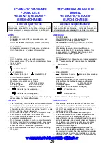
SCHEMATIC DIAGRAMS

FOR MODELS

ZEICHENERKLÄRUNG FÜR

MODELL

TX-29AS1D,TX-29AS1F

TX-29AS1D,TX-29AS1F

(EURO-4 CHASSIS)

(EURO-4 CHASSIS)

NOTES

ANMERKUNG

1.  RESISTOR

All resistors are carbon ¼W resistor, unless marked
otherwise.
Unit of resistance is OHM (

) (k=1,000, M=1,000,000)

1.  WIDERSTÄNDE

Alle ¼W Widerstände sind Kohlewiderstände,
Abweichungen sind folgt gekennzeichnet.
Die Maßeinheit ist OHM (

) (k=1,000, M=1,000,000)

2.  CAPACITORS

All capacitors are ceramic 50V unless marked otherwise.
Unit of capacitance is 

µ

F unless otherwise stated.

2.  KONDENSATOREN

Alle Kondensatoren sind Keramikausführungen.
Spannungsfestigkeit 50V. Abweichungen sind wie folgt
gekennzeichnet. Die Maßeinheit ist 

µ

F, wenne keine

anderen Bezeichnungen gennant sind.

3.  COIL

Unit of inductance is 

µ

H, unless otherwise stated.

3.  SPULEN

Die Maßeinheit ist 

µ

H, Abweichungen sind gekennzeichnet.

4.  Components marked "L" on the schematic diagram shows

leadless parts.

4.  Mit "L" gekennzeichnete Teile sind ohne Anschlußdrähte.

5.  TEST POINT

Test Point Position

5. 

TESTPUNKTE

Kennzeichnung der Testpunktposition

6.  EARTH SYMBOL

Chassis Earth (Cold)

Line Earth (Hot)

6.  MASSE SYMBOL

Erdung am Chassis

Erdung an Masse-Leitung

7.  VOLTAGE MEASUREMENT

Voltage is measured by a d.c. voltmeter.
Measurement conditions are as follows:
Power source

a.c. 220V-240V, 50Hz

Receiving Signal

Colour Bar signal (RF)

All customer controls

Maximum position

7.  SPANNUNGSMESSUNG

Spannungsmessungen sind mit einem d.c.-Voltmeter
durchzuführen. Die Meßbedingungen sind folgende:
Netzspannung 

a.c. 220V-240V, 50Hz

Wiedregabe Signal 

Farbbalken-Testbild

Wiedergabesignal Farbbalken-Testbild (HF)

8. 

Indicates the Video signal path

Indicates the Audio signal path

8. 

Videosignalweg

Audiosignalweg

These schematic diagrams are the latest at time of printing 
and are subject to change without notice.

Änderungen im Laufe der Fertigung sind möglich.

REMARKS

BEMERKUNGEN

1.  The Power Supply Circuit contains a circuit area which uses

a separate power supply to isolate the earth connection.
The circuit is defined by HOT and COLD indications in the 
schematic diagram. All circuits except the Power Circuit, are
COLD. Take the following precautions :-

1.  Das Schaltnetzteil enthält Bereiche, die direkt mit dem 

Netz verbunden sind. Diese Bereiche sind im Schaltplan 
mit HOT gekennzeichnet. Alle anderen Schaltungen sind
mit COLD gekennzeichnet und haben keine direkte 
Verbindung mit den Netz :-

a.  Do not touch the hot part, or the hot and cold parts at the

same time, as you are liable to a shock hazard.

b.  Do not short circuit the hot and cold circuits as electrical 

components may be damaged.

c.  Do not connect an instrument, such as an oscilloscope, to 

the hot and cold circuits simutaneously as this may cause 
fuse failure. Connect the earth of the instruments to the 
earth connection of the circuit being measured.

d.  Make sure to disconnect the power plug before removing

the chassis.

a.  Weder die Leitungen im heißen noch Leitungen im
b.  heißen und im kalten Bereich gleichzeitig berühren. Es 

besteht die Gefahr eines elektrischen Schlages.

c.  Keinesfalls die Leitungen im heißen Bereich mit denen im 

kalten Bereich verbinden oder kurzschliessen. Dies kann
zur Zerstörung von Bauteilen oder Sicherungen führen. 
Außerdem ist die elektrische Betriebssicherheit des 
Gerätes nicht mehr gegeben.
Keine Messinstrumente gleichzeitig an Leitungen im
heissen und kalten Bereich anschliessen. Sicherungen
könnten zerstört werden. Die Erde des Messinstrumentes 
immer mit der des zu prüfenden Schaltkreises verbinden.

d.  Vor Ausbau des Chassis, Stecker aus der Netzsteckdose 

ziehen.

26

IMPORTANT SAFETY NOTICE

Components identified by

mark 

have 

special

characteristics  important  for  safety.  When  replacing  any  of
these components, use only manufacturer's specified parts.

WICHTIGER SICHERHEITSHINWEIS

Teile, die mit einen Hinweis

gekennzeichnet 

sind,

sind  wichtig  für  die  Sicherheit,  Sollte  ein  Auswechsein
erforderlich sein, sind unbedingt Originalteile einzusetzen.

www.rtv-horvat-dj.hr

www.rtv-horvat-dj.hr

Summary of Contents for QuintrixF TX-29AS1D

Page 1: ...OTE This Service Manual should be used in conjunction with the EURO 4 technical guide TECHNISCHE DATEN Netzpannung 220 240V a c 50Hz Leistungsaufnahme 110W Standby Leistungsaufnahme 1 4W Antennenimpedanz 75Ω asymmetrisch Koaxial Typ Empfangssystem PAL I B G H D K PAL 525 60 SECAM B G D K L L M NTSC nur AV Eingang NTSC nur AV Eingang Empfangsbereiche VHF E2 E12 VHF H1 H2 ITALY VHF A H ITALY VHF R1 ...

Page 2: ...ng should be between 4M ohm and 20M ohm When the exposed metal does not have a return path to the chassis the reading must be infinite SICHERHEITSVORKEHRUNGEN ALLGEMEINE RICHTLINIEN 1 Es ist empfehlenswert einen Trenntransformator in die Stromversorgung zu schalten bevor Reparaturen an einem Gerät vorgenommen werden dessen Chassis unter Spannung steht 2 Bei der Durchführung von Servicearbeiten dür...

Page 3: ...stand in Serie mit einem von außen zugänglichen Metallteil am Fernsehgerät und einer guten Erdung z B Wasserleitung anschließen 3 Ein Wechselstrom Voltmeter mit einem Meßbereich von 1000 Ohm Volt oder größer verwenden um die Spannung über den Widerstand zu messen 4 Jedes zugängliche Metallteil prüfen und an jedem Punkt dies Spannung messen 5 Den Netztecker umgekehrt in die Steckdose stecken und je...

Page 4: ...E ENTFERNEN DER GERÄTERÜCKWAND 1 Die 8 Schrauben entfernen siehe Abb 2 LOCATION OF CONTROLS LAGE DER EINSTELLREGLER 4 Fig 2 Abb 2 SCREWS SCHRAUBEN SCREWS SCHRAUBEN Fig 3 Abb 3 M Board Y Board E Board H Board Focus Fokusregler Screen Schirmgitteregler P Board www rtv horvat dj hr www rtv horvat dj hr ...

Page 5: ...ng the receiver to the customer SERVICE POSITION FÜR DAS CHASSIS 1 Die 2 Schrauben A entfernen wie in Abb 4 dargestellt und die Lautsprechereinheit herausnehmen 2 Das Chassis leicht anheben und nach hinten herausziehen wie in Abb 5 dargestellt 3 Die Befestigungen des Hochspannungskabels lösen und das Kabel zur linken Seite des Röhrenhalses legen 4 Das Chassis wie in Abb 6 gezeigt herausheben 5 Mit...

Page 6: ...tives Training bereitstellt ermöglicht es einen noch schnelleren Zugang zu technischen Informationen Verlängerungskabelvorrichtung zur Verbindung Y2 E8 Abb 6 Bestell Nr TZS9EK012 Service Aids To aid in the service of our current chassis there are a number of Service Aids which have been made available LUCI interface kit Linked Utility Computer Interface Part number TZS6EZ002 This contains interfac...

Page 7: ...nt and adjust the screen VR until the display shows O K ABGLEICH Vorbereitungen Abgleich B Abgleich 1 Testbild empfangen Helligkeit auf Minimum Kontrast auf Minimum Lautstärke Minimum 1 Folgende Spannungen sind zu überprüfen B2 148 1V B9 5 0 25V B10 5 0 25V B5 12 0 5V B11 33 1 5V B4 15 5 1V B7 8 0 5V B12 26 1V B8 5 75 0 5V B3 36 1 5V B13 13 1V B1 215 10V B14 13 1V Cut Off Ug2 Test 1 Testbild empfa...

Page 8: ...WAVEFORM PATTERN TABLE SIGNAL TABELLE 8 CONDITIONS CONTRAST MAX BRIGHTNESS MID COLOUR MID SHARPNESS MID www rtv horvat dj hr www rtv horvat dj hr ...

Page 9: ...plitude H Amp 042 Optimum setting Vert Amplitude V Amp 072 Optimum setting EW amplitude EW Amp1 051 Optimum setting EW amplitude EW Amp2 012 Optimum setting Trapezium comp Trapez 1 047 Optimum setting Trapezium comp Trapez 2 005 Optimum setting Vertical Linearity V Lin 034 Optimum setting Vertical Symmetry V Sym 002 Optimum setting DVCO DVCO 007 Receive a PAL Colour Bar Pattern For DVCO alignment ...

Page 10: ...g Horizontale Amplitude H Amp 042 Optimale Einstellung Vertikale Amplitude V Amp 072 Optimale Einstellung OW amplitude EW Amp1 051 Optimale Einstellung OW amplitude EW Amp2 012 Optimale Einstellung Trapez Kompensation Trapez 1 047 Optimale Einstellung Trapez Kompensation Trapez 2 005 Optimale Einstellung Vertikale linearität V Lin 034 Optimale Einstellung Vertikale Symmetrie V Sym 002 Optimale Ein...

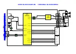
Page 11: ... Q351 CRT 3 2 1 7 8 9 Y2 4 3 5 IC351 TUNER Q104 Red 15 Blue 7 Green 11 Video In 20 AV2 C 15 Video Out 19 G OUT 38 R OUT 37 G IN 46 R IN 45 Q306 Q304 Q302 Q3001 G 38 B 39 Y BOARD E BOARD RGB OUTPUT VIDEO PROCESSOR MICRO PROCESSOR E15 6 8 H1 H3 E61 1 1 6 8 H BOARD IC3401 8 6 3 VIDEO SWITCHING 2 4 2 4 Q3201 Q3202 Q3207 M2 E17 6 6 AV3 Y C M BOARD M3 4 2 8 6 H2 4 2 8 6 Q3208 Q3209 Q3402 Q3203 Q3204 Q32...

Page 12: ...ANA_IN1 44 MONO IN DACM_L 25 SC3_IN_R 38 SC1_IN_R 42 SC1_IN_L 41 SC2_OUT_R 27 SC2_OUT_L 28 SC2_IN_R 40 SC2_IN_L 39 E BOARD AUDIO PROCESSOR AUDIO MONITOR OUT Q103 49 ANA_IN2 X101 X102 Q2302 22 DACA_L Q2304 21 DACA_R E16A 1 M1 1 2 2 AV3 R 4 R 2 L HEADPHONE 3 R 1 L M4 1 M5 3 E17 10 M2 10 8 8 M BOARD IC251 Q2102 Q2103 5 R R 7 2 L L 11 AUDIO OUTPUT L www rtv horvat dj hr www rtv horvat dj hr ...

Page 13: ...T KEYSCAN ON OFF R C L E D PROT 1 SLOW 2 OUT IN SLOW 1 SERVICE SCL SDA 48 49 SCL SDA H BOARD E BOARD 3 IC3401 VIDEO SWITCHING IC2101 8 7 4 AUDIO PROCESSOR MICRO PROCESSOR VIDEO PROCESSOR IC1103 6 5 EAROM Q1051 M1 6 E16A 8 7 7 M2 5 E17 5 IC1061 REMOTE CONTROL RECEIVER D1061 Q1062 LOCAL KEYS SWITCH MATRIX M BOARD 78 79 MIX SW CHROMA SW 8 5 6 Q3204 Q3202 Q3203 Q3201 Q3205 Q3206 5 Q3401 D_CTR_OUTO 61 ...

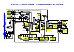
Page 14: ...V 16 IC1104 2 RESET MICRO PROCESSOR AUDIO PROCESSOR VIDEO PROCESSOR EPROM EAROM IC1105 2 RESET REG REG REG IC3401 7 VIDEO SWITCHING IC701 6 EW CORRECTION POWER SUPPLY IC451 6 3 1 V OUTPUT AUDIO OUTPUT D801 E BOARD Y BOARD E3 2 Y3 2 E1 4 1 E2 2 1 Line Filter E62 1 H3 2 IC351 6 RGB OUTPUT 12V Degauss Coil F802 S802 M10 4 1 Line Filter Mains In M BOARD M1 9 E16A 9 IC1061 REMOTE CONTROL RECEIVER P BOA...

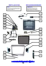
Page 15: ...3 NOTE The numbers on the exploded view below refer to the exploded view section of the Replacement Parts List ANMERKUNG Die Nummern auf den Teilen der Explosionszeichnung zeigen die Bezugsnummern des Artikels der Explosionszeichnung der Ersatzteilliste an www rtv horvat dj hr www rtv horvat dj hr ...

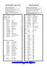
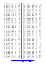
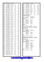
Page 16: ...ORN TKXA04001A CANCELLATION COIL TLK8E05150 GEOMAGNETIC COIL TLK8E05164 LED HOLDER TMW8E020 1 PCB BRACKET TMX8E041 OUTER CARTON TPC8E4848 TOP CUSHON TPD8E741 BOTTOM CUSHION TPD8E742 BATTERY PACK UM 3DJ 2P 84 PIN IC SOCKET IC1101S PLCC 84 T CRT SOCKET S351 0330550049 I C s AUDIO OUTPUT IC251 LA4282 R G B OUTPUT IC351 TDA6103Q N3 VERTICAL OUTPUT IC451 LA7845N VIDEO PROCESSOR IC601 VDP3112BPPC2 E W C...

Page 17: ...706 THERMISTOR R843 232266296706 TRANSISTORS TRANSISTOR Q101 BC847B TRANSISTOR Q102 BC847B TRANSISTOR Q103 BC847B TRANSISTOR Q104 BC847B TRANSISTOR Q105 BC847B TRANSISTOR Q251 2SD1328STX TRANSISTOR Q252 2SD1328STX TRANSISTOR Q253 BC847B TRANSISTOR Q254 BC847B TRANSISTOR Q301 BC847B TRANSISTOR Q302 FMY4T148 TRANSISTOR Q303 BC847B TRANSISTOR Q304 FMY4T148 TRANSISTOR Q305 BC847B TRANSISTOR Q306 FMY4T...

Page 18: ...ARB JA2 ERJ8GEY0R00 125W 5 0 S M CARB JA3 ERJ6GEY0R00 0 1W 5 0 S M CARB JA5 ERJ8GEY0R00 125W 5 0 S M CARB JA8 ERJ8GEY0R00 125W 5 0 S M CARB JA9 ERJ6GEY0R00 0 1W 5 0 S M CARB JA10 ERJ6GEY0R00 0 1W 5 0 S M CARB JA11 ERJ6GEY0R00 0 1W 5 0 S M CARB JA12 ERJ6GEY0R00 0 1W 5 0 S M CARB JA13 ERJ6GEY0R00 0 1W 5 0 S M CARB JA14 ERJ6GEY0R00 0 1W 5 0 S M CARB JA15 ERJ6GEY0R00 0 1W 5 0 S M CARB JA16 ERJ6GEY0R00...

Page 19: ... M CARB R312 ERJ6GEYJ331 0 1W 5 330 S M CARB R351 ERJ6GEYJ302 0 1W 5 3K S M CARB R352 ERJ6GEYJ302 0 1W 5 3K S M CARB R353 ERJ6GEYJ302 0 1W 5 3K S M CARB R354 ERJ6GEYJ102 0 1W 5 1K S M CARB R355 ERJ6GEYJ102 0 1W 5 1K S M CARB R356 ERJ6GEYJ102 0 1W 5 1K METAL R357 ERG12DJ114V 0 5W 5 110K METAL R358 ERG12DJ114V 0 5W 5 110K METAL R359 ERG12DJ114V 0 5W 5 110K CARBON R363 ERD25TJ103 0 25W 5 10K CARBON R...

Page 20: ... 0 1W 5 47K S M CARB R914 ERJ6GEYJ822 0 1W 5 8K2 S M CARB R915 ERJ6GEYJ152 0 1W 5 1K5 S M CARB R916 ERJ6GEYJ391 0 1W 5 390 FUSIBLE R919 ERQ14AJW390 0 25W 5 39 FUSIBLE R920 ERQ14AJW390 0 25W 5 39 CARBON R921 ERDS2TJ471T 0 5W 5 470 CARBON R922 ERD25TJ393 0 25W 5 39K CARBON R923 ERD25TJ393 0 25W 5 39K CARBON R924 ERDS1FJ390 0 5W 5 39 S M CARB R925 ERJ6GEY0R00 0 1W 5 0 S M CARB R926 ERJ6GEY0R00 0 1W 5...

Page 21: ...100K S M CARB R2309 ERJ6GEYJ101 0 1W 5 100 S M CARB R2310 ERJ6GEYJ471 0 1W 5 470 S M CARB R2311 ERJ6GEYJ102 0 1W 5 1K S M CARB R2312 ERJ6GEYJ103 0 1W 5 10K S M CARB R3001 ERJ6GEYJ101 0 1W 5 100 S M CARB R3002 ERJ6GEYJ471 0 1W 5 470 S M CARB R3003 ERJ6GEYJ101 0 1W 5 100 S M CARB R3004 ERJ6GEYJ153 0 1W 5 15K S M CARB R3005 ERJ6GEYJ101 0 1W 5 100 S M CARB R3006 ERJ6GEYJ471 0 1W 5 470 S M CARB R3007 E...

Page 22: ...ELECT C267 ECJ2YB1H104K 50V 100nF ELECT C268 ECJ2YB1H104K 50V 100nF ELECT C270 ECJ2YB1H104K 50V 100nF ELECT C301 ECJ2VB1C104K 350V 100nF ELECT C302 ECJ2VB1C104K 350V 100nF ELECT C303 ECJ2VB1C104K 350V 100nF ELECT C304 ECEA1CU100 16V 10µF FILM C354 ECQM2104KZ 250V 100nF S M CAP C355 ECUV1H222JCX 50V 2 2nF S M CAP C356 ECUV1H222JCX 50V 2 2nF S M CAP C357 ECUV1H222JCX 50V 2 2nF FILM C358 ECQV1H224JL3...

Page 23: ... 7nF S M CAP C906 ECUV1H471KBX 50V 470pF S M CAP C908 ECUV1H151JCX 50V 150pF CERAMIC C909 ECKC2H472J 500V 4 7nF CERAMIC C910 ECKC2H472J 500V 4 7nF S M CAP C911 ECUV1H151JCX 50V 150pF ELECT C912 ECEA2CU100 160V 10µF ELECT C913 ECEA1HU101 50V 100µF ELECT C914 ECEA1HU101 50V 100µF ELECT C916 ECEA2CGE100 160V 10µF ELECT C950 ECJ2VB1C104K 350V 100nF ELECT C1061 ECJ2VB1H103K 350V 10nF ELECT C1062 ECEA1H...

Page 24: ...CX 50V 270pF ELECT C3101 ECJ2YB1H104K 50V 100nF ELECT C3102 ECJ2VB1E104K 350V 100nF S M CAP C3111 ECUV1H222KBX 50V 2 2nF S M CAP C3112 ECUV1H271JCX 50V 270pF ELECT C3201 ECJ2VB1H103K 350V 10nF ELECT C3202 ECJ2VB1H103K 350V 10nF S M CAP C3203 ECUV1H561JCX 50V 560pF S M CAP C3204 ECUV1H561JCX 50V 560pF ELECT C3205 ECEA1HU470 50V 47pF S M CAP C3206 ECUV1H561JCX 50V 560pF S M CAP C3207 ECUV1H561JCX 50...

Page 25: ...Circuit contains a circuit area which uses a separate power supply to isolate the earth connection The circuit is defined by HOT and COLD indications in the schematic diagram All circuits except the Power Circuit are COLD Take the following precautions 1 Das Schaltnetzteil enthält Bereiche die direkt mit dem Netz verbunden sind Diese Bereiche sind im Schaltplan mit HOT gekennzeichnet Alle anderen ...

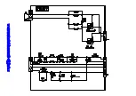
Page 26: ...www rtv horvat dj hr www rtv horvat dj hr ...

Page 27: ...www rtv horvat dj hr www rtv horvat dj hr ...

Page 28: ...www rtv horvat dj hr www rtv horvat dj hr ...

Page 29: ...www rtv horvat dj hr www rtv horvat dj hr ...

Page 30: ...www rtv horvat dj hr www rtv horvat dj hr ...

Page 31: ...D904 C2 Q907 C3 D905 C3 Q908 D2 D906 D3 Q909 D2 D907 C3 DIODES IC S D354 B3 IC351 A2 D355 A3 TP S D356 B3 TPY1 B3 D357 B3 TPY2 B2 D358 B3 TPY3 B3 D359 B3 TPY4 C2 D360 A2 TPY5 C2 D361 B1 TPY6 A1 H BOARD TNP8EH002 TRAN S Q3401 C2 Q3402 A2 IC S IC3401 B2 A B C D 1 2 3 A B C 1 2 3 33 www rtv horvat dj hr www rtv horvat dj hr ...

Page 32: ...P BOARD TNP8EP018 DIODES D580 B3 A B C D 1 2 3 E 34 www rtv horvat dj hr www rtv horvat dj hr ...

Reviews: