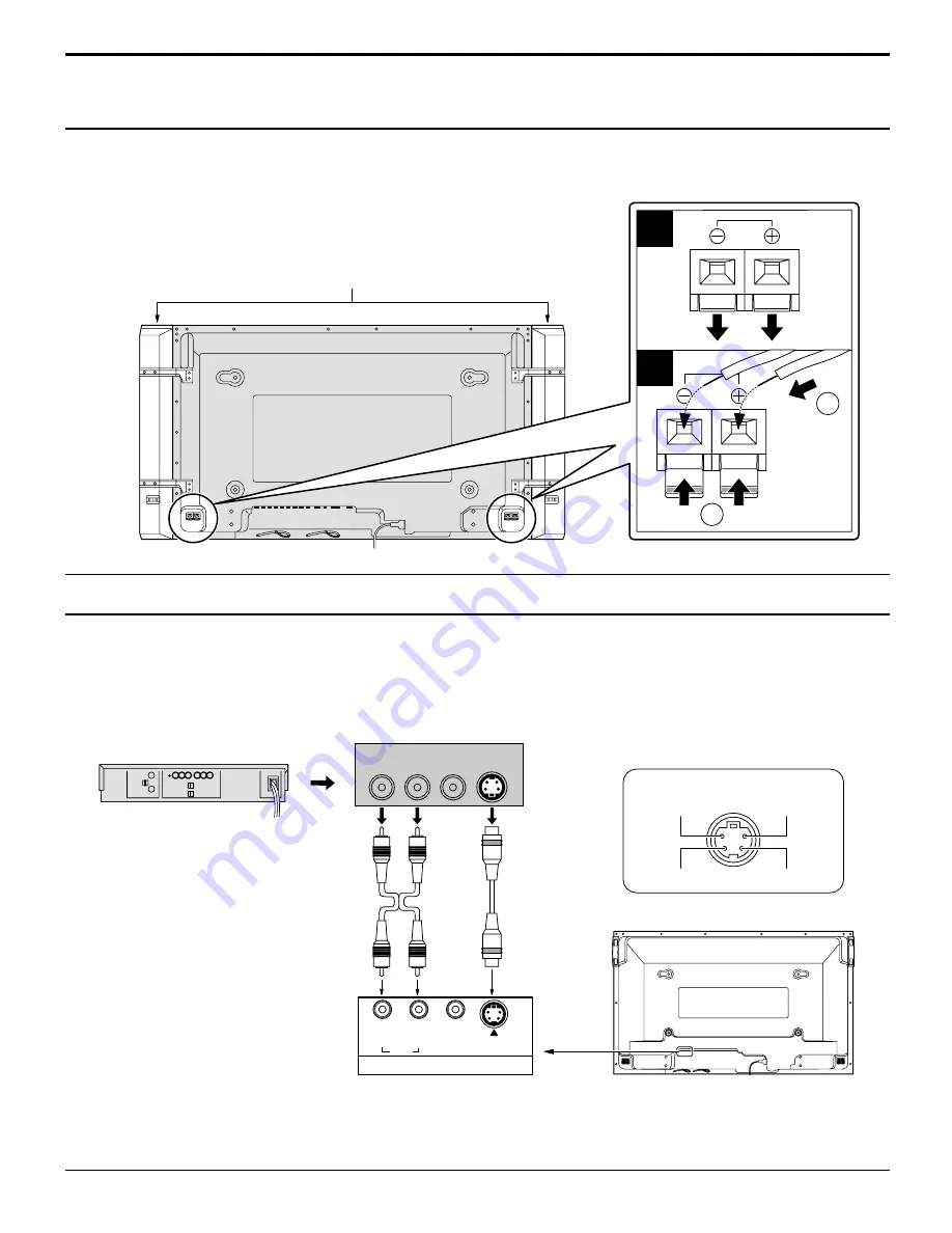
background image

13

Connections

Speakers connection

When connecting the speakers, be sure to use only the optional accessory
speakers.
Refer to the speaker’s Installation Manual for details on speaker installation.

Luminance earth

Luminance in

Chrominance earth

Chrominance in

S VIDEO 4 pin socket

(S VIDEO VCR)

S VIDEO

Video input to

S VIDEO

socket

Audio input to

L/R sockets

AUDIO

2

×

RCA audio

cables

Audio

OUT

Video

OUT

S Video

OUT

R

L

AV  IN

S  VIDEO

VIDEO

R

L

AUDIO

AV Input Terminals connection

Connect the signal source equipment (see page 14 to 17).

(Example) When connecting an S VIDEO VCR

1

1

2

2

Speakers (Optional accessories)

Notes:
(1) Change the “COMPONENT/RGB-IN” setting in the “SET UP” menu to “RGB”. (see page 32, 34)
(2) Additional equipment and cables shown are not supplied with this set.

Summary of Contents for PT42PD3P - PLASMA DISPLAY

Page 1: ...roduct please read these instructions completely Please keep this manual for future reference English For assistance please call 1 888 VIEW PTV 843 9788 or send e mail to consumerproducts panasonic com or visit us at www panasonic com U S A For assistance please call 787 750 4300 Puerto Rico For assistance please call 1 800 561 5505 or visit us at www panasonic ca Canada ...

Page 2: ...d within a triangle is intended to tell the user that parts inside the product are a risk of electric shock to persons The exclamation point within a triangle is intended to tell the user that important operating and servicing instructions are in the papers with the appliance WARNING To reduce the risk of electric shock do not remove cover or back No user serviceable parts inside Refer servicing t...

Page 3: ...ns have been adhered to 9 Do not defeat the safety purpose of the polarized or grounding type plug A polarized plug has two blades with one wider than the other A grounding type plug has two blades and a third grounding prong The wide blade or the third prong are provided for your safety If the provided plug does not fit into your outlet consult an electrician for replacement of the obsolete outle...

Page 4: ...on S VGA is a registered trademark of the Video Electronics Standard Association Even if no special notation has been made of company or product trademarks these trademarks have been fully respected For assistance please call 1 888 VIEW PTV 843 9788 or send e mail to consumerproducts panasonic com or visit us at www panasonic com U S A For assistance please call 787 750 4300 Puerto Rico For assist...

Page 5: ...on 18 AC cord connection 18 Power ON OFF 18 Select the Input Signal 19 Selecting the ON Screen Menu Language 19 On Screen Menu Display from Remote Control 20 ASPECT Controls 22 ADJUSTING PICTURE POS SIZE 24 SOUND ADJUSTMENT 26 MUTE 26 SURROUND Controls 27 PICTURE Adjustments 28 SCREENSAVER For preventing after images 30 NEGATIVE SCROLL Selection 30 ON OFF Selection 30 SIDE BAR ADJUST 31 SET UP for...

Page 6: ... from that to which the receiver is connected Consult the dealer or an experienced radio TV technician for help This device complies with Part 15 of the FCC Rules Operation is subject to the following two conditions 1 This device may not cause harmful interference and 2 this device must accept any interference received including interference that may cause undesired operation FCC CAUTION To assure...

Page 7: ... they should not be used Do not handle the power cord plug with wet hands Doing so may cause electric shocks Do not do anything that might damage the power cable When disconnecting the power cable hold the plug not the cable Do not make any modifications place heavy objects on place near hot objects heat bend twist or forcefully pull the power cable Doing so may cause damages to the power cable wh...

Page 8: ...e fire Unplug the cord from the wall outlet and clean it with a dry cloth Cleaning and maintenance The front of the display panel has been specially treated Wipe the panel surface gently using only a cleaning cloth or a soft lint free cloth If the surface is particularly dirty soak a soft lint free cloth in a weak detergent solution and then wring the cloth to remove excess liquid Use this cloth t...

Page 9: ...42PWD3W Pedestal TY ST42PT3 K Wall stand TY ST42PW1 Connecting Cable TY SCP15C03 49 2 ft 15 m Ferrite core J0KF00000018 2 Batteries for the Remote Control Transmitter AA R6 Battery 2 For assembling Full instructions are supplied with each optional accessories for use with this Plasma Display AC cord Warranty Wall hanging bracket angled TY WK42PR1 Remote Control Transmitter EUR646525 Operating Inst...

Page 10: ...installation can cause battery leakage and corrosion that will damage the remote control transmitter Observe the following precautions 1 Batteries should always be replaced as a pair Always use new batteries when replacing the old set 2 Do not combine a used battery with a new one 3 Do not mix battery types example Zinc Carbon with Alkaline 4 Do not attempt to charge short circuit disassemble heat...

Page 11: ...VIDEO COMPONENT RGB PC Mode Selection Press to select VIDEO S VIDEO COMPONENT or RGB PC input signal modes sequentially see page 19 Sound mute On Off see page 26 Volume Adjustment Press the Volume Up or Down button to increase or decrease the sound volume level ACTION button Press to make selections ASPECT button Press to adjust the aspect see page 22 SOUND button see page 26 SET UP button see pag...

Page 12: ...as required SPEAKER Terminals L From SERIAL Terminal on Computer see page 17 From EXIT monitor Terminal on Computer see page 16 COMPONENT RGB IN and Audio IN Terminals see page 14 15 AV IN Terminals see page 13 14 Pass the attached cable fixing band through the clip as shown in the figure To secure cables connected to Terminals wrap the cable fixing band around them then pass the pointed end throu...

Page 13: ...VIDEO VCR S VIDEO Video input to S VIDEO socket Audio input to L R sockets AUDIO 2 RCA audio cables Audio OUT Video OUT S Video OUT R L AV IN S VIDEO VIDEO R L AUDIO AV Input Terminals connection Connect the signal source equipment see page 14 to 17 Example When connecting an S VIDEO VCR 1 1 2 2 Speakers Optional accessories Notes 1 Change the COMPONENT RGB IN setting in the SET UP menu to RGB see...

Page 14: ...IDEO R L AUDIO VCR PR CR R PB CB B Y G COMPONENT RGB IN VD HD R L AUDIO R L Y PB PR AUDIO 3 RCA video cables 2 RCA audio cables DVD Player Y PB PR Notes 1 Change the COMPONENT RGB IN setting in the SET UP menu to RGB see page 32 34 2 Additional equipment and cables shown are not supplied with this set Notes 1 Change the COMPONENT RGB IN setting in the SET UP menu to RGB see page 32 34 2 Additional...

Page 15: ...tor plugs shown are not supplied with this set COMPONENT RGB IN R L AUDIO Audio input to L R sockets G B R VD HD AUDIO 2 RCA audio cables 5 BNC RGB cables RGB input to R G B HD VD sockets BNC RCA adaptor plug Example of input signal source HDTV compatible VCR Computer RGB camera VD HD PR CR R PB CB B Y G RGB signal R G B HD VD connection ...

Page 16: ...n adapter for computers with DOS V compatible D sub 15P terminal 6 The computer shown in the illustration is for example purposes only 7 Additional equipment and cables shown are not supplied with this set 8 Do not set the horizontal and vertical scanning frequencies for PC signals which are above or below the specified frequency range Signal Names for D sub 15P Connector AUDIO PC IN COMPUTER Conv...

Page 17: ...s 9600 bps None 8 bits 1 bit Communication parameters RS 232C Conversion cable D sub 9 pin female 2 3 5 4 6 7 8 1 9 Details R X D T X D GND Non use Shorted NC Command PON POF AVL AMT IIS DAM Control details Power ON Power OFF Volume 00 63 Audio MUTE OFF Audio MUTE ON Input select toggle AV Mode Component RGB mode processed as a Y PB PR or RGB signals as set by this unit PC mode Screen mode select ...

Page 18: ...Display when the Plasma Display is on or in standby mode Remote Control Sensor INPUT SURROUND VOL N R SELECT OSD LANGUAGE SET English UK Deutsch Fran ais Italiano Espa ol ENGLISH US R STANDBY G POWER ON INPUT VOL R STANDBY G POWER ON TY 42PW4 Power Indicator Power ON OFF and Input Signal Selection When the POWER is turned on for the first time the LANGUAGE selection screen is displayed From the se...

Page 19: ...ut signals will change as follows For COMPONENT INPUT see page 32 For RGB INPUT see page 32 VIDEO COMPONENT PC VIDEO RGB PC Selecting the On Screen Menu Language SET UP SIGNAL SCREENSAVER COMPONENT RGB IN SELECT RGB OSD LANGUAGE ENGLISH US press to display the SET UP menu press to select your preferred language selectable languages English UK Deutsch Français Italiano Español ENGLISH US Chinese SU...

Page 20: ...LIZE AUDIO MENU BASS TREBLE STANDARD ON 0 0 0 BALANCE SURROUND NORMAL To PICTURE POS SIZE adjust menu see page 24 During VIDEO and COMPONENT input signal modes NORMAL PICTURE POS SIZE NORMALIZE H POS H SIZE V POS V SIZE To SET UP menu see page 32 SET UP SIGNAL SCREENSAVER COMPONENT RGB IN SELECT RGB OSD LANGUAGE ENGLISH US SET UP SIGNAL SCREENSAVER COMPONENT RGB IN SELECT RGB OSD LANGUAGE ENGLISH ...

Page 21: ...3D Y C FILTER NTSC COLOR SYSTEM Panasonic AUTO 4 3 ON AUTO NORMAL SIGNAL VIDEO SIGNAL RGB SYNC PULL IN RANGE H V NARROW CLAMP POSITION SIGNAL PC SYNC PULL IN RANGE H V NARROW CLAMP POSITION Press to access SCREENSAVER menu see page 30 R Press the R buttun to return to SET UP menu R Press the R buttun to return to SET UP menu SCREENSAVER FUNCTION MODE WHITE BAR SCROLL ON SIDE BAR ADJUST OFF To setu...

Page 22: ...T ASPECT Notes 1 During RGB and PC input signal modes the mode switches between NORMAL ZOOM and FULL only 2 For a 525p 480p signal input during COMPONENT input signal mode the mode switches between ZOOM and FULL only 3 For a 1125i 1080i 750p 720p signal input during COMPONENT input signal mode the mode is set to FULL mode and switching is not possible For a 525i 480i 625i 575i signal input during ...

Page 23: ...can detect specially encoded signals that are compatible with a wide screen monitor When a full image from the S VIDEO terminal of specially encoded video is detected by the set the screen size is automatically set to FULL mode NORMAL 3 4 ZOOM 4 3 16 9 FULL 4 3 16 9 4 3 9 16 JUST Picture The display will automatically become enlarged depending on the picture source allowing you to view the picture...

Page 24: ... signal formats Adjustments for component signals are memorized for 525i 480i 625i 575i 525p 480p 1125i 1080i and 625p 575p 750p 720p each and RGB PC signals are memorized for each frequency 2 If a Cue or Rew signal from a VCR or DVD player is received the picture position will shift up or down This picture position movement cannot be controlled by the PICTURE POS SIZE function R Press to exit fro...

Page 25: ... by using the Position Left or Right button to carry out adjustment Helpful Hint NORMALIZE Normalization While the PICTURE POS SIZE display is active if either the N button on the remote control is pressed at any time or the ACTION button is pressed during NORMALIZE then all adjustment values are returned to the factory settings When the Position Left button is pressed When the Position Left butto...

Page 26: ...r is turned off or volume level is changed SURROUND VOL N R PICTURE SET UP PICTURE POS S INPUT SOUND R While the SOUND menu is displayed if either the N button on the remote control is pressed at any time or the ACTION button is pressed during NORMALIZE then all adjustment values are returned to the factory settings Helpful Hint NORMALIZE Normalization N To end adjustments Note Press the SURROUND ...

Page 27: ...if you were at a concert hall or cinema The surround setting switches on and off each time the SURROUND button is pressed ON OFF Note The surround settings are memorized separately for each SOUND mode AUTO STANDARD PLASMA DISPLAY VOL N R PICTURE SET UP PICTURE POS SIZE OFF TIMER PC INPUT ASPECT SOUND SURROUND SURROUND ON SURROUND ...

Page 28: ...ng in standard evening lighting environments This menu selects the normal levels of BRIGHTNESS and PICTURE DYNAMIC For viewing in brighter environments This menu selects higher than normal levels of BRIGHTNESS and PICTURE CINEMA Ideal for movies Can be selected for VIDEO COMPONENT Press the left or right button to switch between modes NORMAL COOL WARM While the PICTURE menu is displayed if either ...

Page 29: ...age Notes 1 COLOR TINT and SHARPNESS settings cannot be adjusted for RGB and PC input signal modes 2 You can change the level of each function PICTURE BRIGHTNESS COLOR TINT SHARPNESS for each PICTURE menu 3 The setting details for normal dynamic and cinema respectively are memorized separately for each input mode VIDEO COMPONENT RGB 4 The TINT setting can be adjusted for NTSC signal only Less More...

Page 30: ...Press to select the Function Press to select the desired function NEGATIVE WHITE BAR SCROLL NEGATIVE Negative image will be displayed on the screen WHITE BARSCROLL The white bar will scroll from left to right Press to select the MODE Press to select ON or OFF Do not display a still picture especially in 4 3 mode for any length of time If the display must remain on a SCREENSAVER should be used ON O...

Page 31: ...d as this can cause an after image to remain on the side bars either side of the display field To prevent the appearance of such an after image illuminate the side bars To display the SCREENSAVER screen Refer to the previous page operation guide steps 1 and 2 SCREENSAVER Notes Setting the side bar to BRIGHT mode for an extended period may result in occurence of after images The side bars may flash...

Page 32: ...de COMPONENT RGB R Press to exit from adjust mode 3D Y C FILTER For NTSC Video images Select SIGNAL from the SET UP menu during VIDEO input signal mode SIGNAL VIDEO menu is displayed 3D Y C FILTER NTSC COLOR SYSTEM Panasonic AUTO 4 3 ON AUTO NORMAL SIGNAL VIDEO Press to select the 3D Y C FILTER NTSC Press to set ON OFF R Press to exit from adjust mode Press ACTION button Note When on this setting ...

Page 33: ...ly Set to NORMAL to view 4 3 images in an unchanged format when Panasonic AUTO is selected If you would like to view 4 3 images in Just format set to JUST AUTO PAL SECAM M NTSC NTSC 3D Y C FILTER NTSC COLOR SYSTEM Panasonic AUTO 4 3 ON AUTO NORMAL SIGNAL VIDEO Press ACTION button SET UP SIGNAL SCREENSAVER COMPONENT RGB IN SELECT RGB OSD LANGUAGE ENGLISH US If the picture image becomes unstable Wit...

Page 34: ...This setting is the same for both SIGNAL RGB and SIGNAL PC Setting PC sync signal Confirm that the input is set to PC INPUT this setting is valid only for PC INPUT H V The H and V sync signals are input from the HD VD connector ON G Uses a synchronized signal on the Video G signal which is input from the G connector PULL IN RANGE PULL IN RANGE WIDE PULL IN RANGE NARROW Displays the H Horizontal V ...

Page 35: ...Display resulting from fixed image use is not an operating defect and as such is not covered by the Warranty This product is not designed to display fixed images for extended periods of time The display unit is fitted with a cooling fan to dissipate heat generated during normal use The whirring sound is caused by rotation of the fan and is not a malfunction Symptoms Checks Electrical Appliances Ca...

Page 36: ...36 ...

Page 37: ...37 ...

Page 38: ...RCA HD RCA VD RCA AUDIO IN RCA PIN JACK 2 HIGH DENSITY D SUB 15PIN AUDIO IN M3 5 JACK EXTERNAL CONTROL TERMINAL D SUB9PIN 16W 8 W 8 W 10 THD For TY SP42PWD3W only 1 0 Vp p 75 ohm Y 1 Vp p 75 ohm C 0 286 Vp p 75 ohm 0 5 Vrms high impedance 1 0 Vp p composite 75 ohm 0 7 Vp p non composite 75 ohm 0 7 Vp p 75 ohm 0 7 Vp p 75 ohm 1 0 5 0 Vp p high impedance 1 0 5 0 Vp p high impedance 0 5 Vrms high imp...

Page 39: ...ht Mass TH 42PW4 EUR646525 2 AA Size 2 J0KF00000018 2 TMME187 TY SP42PWD3W TY ST42PT3 K TY ST42PW1 TY WK42PR1 TY 42TM4H TY SCP15C03 40 2 1020 mm 24 610 mm 3 5 89 mm approx 65 0 lbs main unit only approx 74 3 lbs with speakers Specifications Note Design and specifications are subject to change without notice Weight and dimensions shown are approximate POWER R STANDBY G POWER ON INPUT VOL 24 610 mm ...

Page 40: ... in identification in the event of theft or loss and for Warranty Service purposes Panasonic Consumer Electronics Company Division of Matsushita Electric Corporation of America One Panasonic Way Secaucus New Jersey 07094 Panasonic Sales Company Division of Matsushita Electric of Puerto Rico Inc PSC Ave 65 de Infanteria Km 9 5 San Gabriel Industrial Park Carolina Puerto Rico 00985 Panasonic Canada ...

Reviews: