Panasonic PT-DZ780 Operating Instructions Manual Download Page 153

Chapter 4

Settings — [NETWORK] menu

ENGLISH - 153

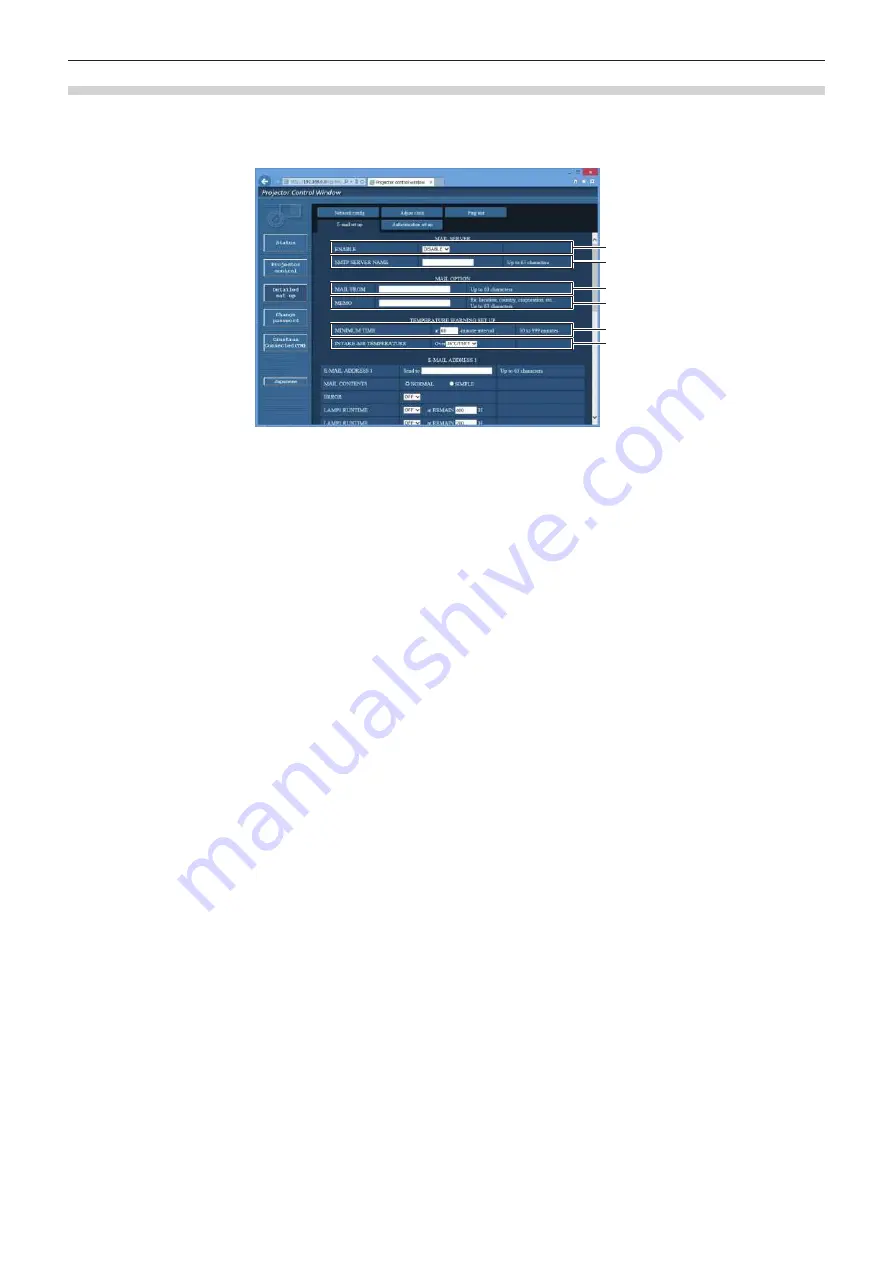
[E-mail set up] page

When there is a problem or the runtime of the lamp reaches a set value, an E-mail can be sent to preset E-mail 

addresses (up to two addresses).
Click [Detailed set up] 

 [E-mail set up].

1

2

3

4

5

6

1  [ENABLE]

Select [Enable] to use the E-mail function.

2  [SMTP SERVER NAME]

Enter the IP address or the server name of the E-mail server 

(SMTP). To enter the server name, the DNS server needs to be 

set up.

3  [MAIL FROM]

Enter the E-mail address of the projector. (Up to 63 characters 

in single byte)

4  [MEMO]

Enter information such as the location of the projector that 

notifies the sender of the E-mail. (Up to 63 characters in single 

byte)

5  [MINIMUM TIME]

Change the minimum interval for the temperature warning 

E-mail. The default value is 60 minutes. In this case, another 

E-mail will not be sent for 60 minutes after sending the 

temperature warning E-mail even if it reaches the warning 

temperature.

6  [INTAKE AIR TEMPERATURE]

Change the temperature setting for the temperature warning 

mail. A temperature warning E-mail is sent when the 

temperature exceeds this value.

Summary of Contents for PT-DZ780

Page 1: ...el the standard zoom lens supplied z for other countries or regions B Black model the standard zoom lens supplied LB Black model the lens sold separately W White model the standard zoom lens supplied LW White model the lens sold separately Before operating this product please read the instructions carefully and save this manual for future use Before using this product be sure to read Read this fir...

Page 2: ...or 55 Connecting the power cord 55 Power indicator 55 Switching on the projector 56 When the initial setting screen is displayed 57 Making adjustments and selections 60 Switching off the projector 61 Direct power off function 61 Projecting 62 Selecting the input signal 62 Adjusting the focus zoom and shift 62 Adjusting the lens position and focus when the fixed focus lens Model No ET DLE030 is use...

Page 3: ...JECTOR ID 111 PROJECTION METHOD 111 COOLING CONDITION 112 LAMP SELECT 112 LAMP RELAY 113 LAMP POWER 113 BRIGHTNESS CONTROL 114 STANDBY MODE 118 SCHEDULE 119 INITIAL STARTUP 120 STARTUP INPUT SELECT 120 RS 232C 121 STATUS 122 NO SIGNAL SHUT OFF 124 REMOTE2 MODE 124 FUNCTION BUTTON 124 DATE AND TIME 124 LENS CALIBRATION 125 SAVE ALL USER DATA 126 LOAD ALL USER DATA 126 INITIALIZE 126 SERVICE PASSWOR...

Page 4: ...en an indicator lights up 162 Maintenance replacement 164 Before performing maintenance replacement 164 Maintenance 164 Replacement 166 Troubleshooting 169 SELF TEST indications 171 Chapter 6 Appendix Technical information 174 PJLink protocol 174 Using Art Net function 175 Control commands via LAN 177 SERIAL IN SERIAL OUT terminal 180 REMOTE 2 IN terminal 184 Two window display combination list 18...

Page 5: ...is a class A product In a domestic environment this product may cause radio interference in which case the user may be required to take adequate measures CAUTION To assure continued compliance follow the attached installation instructions This includes using the provided power cord and shielded interface cables when connecting to computer or peripheral devices Also any unauthorized changes or modi...

Page 6: ... plug Do not remove WARNING USA and Canada f f Not for use in a computer room as defined in the Standard for the Protection of Electronic Computer Data Processing Equipment ANSI NFPA 75 f f For permanently connected equipment a readily accessible disconnect device shall be incorporated in the building installation wiring f f For pluggable equipment the socket outlet shall be installed near the equ...

Page 7: ...omply with the limits for a Class A digital device pursuant to part 15 of the FCC Rules These limits are designed to provide reasonable protection against harmful interference when the equipment is operated in a commercial environment This equipment generates uses and can radiate radio frequency energy and if not installed and used in accordance with the instruction manual may cause harmful interf...

Page 8: ... a new plug is to be fitted please observe the wiring code as shown below If in any doubt please consult a qualified electrician WARNING THIS APPLIANCE MUST BE EARTHED IMPORTANT The wires in this mains lead are colored in accordance with the following code Green and Yellow Earth Blue Neutral Brown Live As the colors of the wire in the mains lead of this appliance may not correspond with the colore...

Page 9: ...r wrap it into a bundle Ask an Authorized Service Center to carry out any repairs to the power cord that might be necessary Do not use anything other than the provided power cord Failure to observe this will result in electric shocks or fire Please note that if you do not use the provided power cord to ground the device on the side of the outlet this may result in electric shocks Completely insert...

Page 10: ... light emitted from the lens while the projector is being used Doing so can cause burns or loss of sight f f Strong light is emitted from the projector s lens Do not look at or place your hands directly into this light f f Be especially careful not to let young children look into the lens In addition turn off the power and switch off the main power when you are away from the projector Do not proje...

Page 11: ...luid on your skin or clothing could result in skin inflammation or injury Rinse with clean water and seek medical advice immediately f f Battery fluid coming in contact with your eyes could result in loss of sight In this case do not rub your eyes Rinse with clean water and seek medical advice immediately Do not disassemble the lamp unit If the lamp breaks it could cause injury Lamp replacement Th...

Page 12: ...esult f f Be especially careful not to let young children stand or sit on the projector Do not place the projector in extremely hot locations Doing so will cause the outer casing or internal components to deteriorate or result in fire f f Take particular care in locations exposed to direct sunlight or near heaters Do not install the projector in a location where salt pollution or corrosive gas may...

Page 13: ...your dealer about replacing the lamp unit and check the inside of the projector When not using the projector for an extended period of time remove the batteries from the remote control Failure to observe this will cause the batteries to leak overheat catch fire or explode which may result in fire or contamination of surrounding area r r MAINTENANCE Do not touch the fan with your fingers or any oth...

Page 14: ...o pela bateria pode irritar a garganta danificar o lacre do invólucro ou o vazamento provocar calor ruptura da blindagem e produzir fogo devido ao curto circuito dos terminais Não incinere nem aqueça as baterias elas não podem ficar expostas a temperaturas superiores a 100 C 212 F O gás liberado pela bateria pode irritar a garganta danificar o lacre do invólucro ou o vazamento provocar calor ruptu...

Page 15: ...ctronics Inc f f HDBaseTTM is a trademark of HDBaseT Alliance f f Art NetTM Designed by and Copyright Artistic Licence Holdings Ltd f f Adobe Adobe Flash Player and Adobe Reader are trademarks or registered trademarks of Adobe Systems Inc in the United States and or other countries f f Some of the fonts used in the on screen menu are Ricoh bitmap fonts which are manufactured and sold by Ricoh Comp...

Page 16: ...rt and lineup of various optional lenses 1 Only for PT DZ780 Reduction of maintenance cost In addition to realizing the long life with lamp replacement recommended time of 6 000H 1 by adopting the dustproof mechanism in the optical block contributes to reduction of the maintenance cost 1 When LAMP POWER is set to ECO Quick Steps For details refer to the corresponding pages 1 Set up the projector x...

Page 17: ...ENGLISH 17 Chapter 1 Preparation This chapter describes things you need to know or check before using the projector ...

Page 18: ...ing so may cause damage to internal components or malfunction f f Location close to sea or where corrosive gas may occur The projector may fall due to corrosion Also it may shorten the life of the components and result in malfunctions f f Near the exhaust of an air conditioner Depending on the conditions of use the screen may fluctuate in rare cases due to the heated air from the air exhaust port ...

Page 19: ...ea level Doing so may shorten the life of the components and result in malfunctions r rDo not use the projector tilted to the right or left Using the projector at a vertical angle that exceeds 15 may reduce product life or result in malfunction r rCautions when setting up the projector f f Use the adjustable feet only for the floor standing installation and for adjusting the angle Using them for o...

Page 20: ... firewall etc f f Set a password for the web control and restrict the users who can log in DIGITAL LINK DIGITAL LINK is a technology to transmit the video audio Ethernet and serial control signals using a twisted pair cable by adding unique functions by Panasonic to the HDBaseTTM communication standard formulated by HDBaseT Alliance This projector supports the optional Panasonic DIGITAL LINK outpu...

Page 21: ...h your bare hands If the surface of the projection lens becomes dirty from fingerprints or anything else this will be magnified and projected onto the screen Attach the lens cover supplied with the projector or with the optional projection lens to the projector when you do not use the projector r rDLP chip f f The DLP chip is precision made Note that in rare cases pixels of high precision could be...

Page 22: ...l TKPB64401 White model TKPB64402 The same color as the outer case will be supplied Lens cover 1 TKKL5244 1 Only models with lens CD ROM 1 TXFQB02WGDZ AAA R03 battery 2 For remote control unit Attention f f After unpacking the projector discard the power cord cap and packaging material properly f f Do not use the supplied power cord for devices other than this projector f f For missing accessories...

Page 23: ... such as company logos to be displayed when projection starts to the projector Optional accessories Optional accessories product name Model No Projection lens Zoom lens ET DLE080 ET DLE085 ET DLE150 ET DLE250 ET DLE350 ET DLE450 Fixed focus lens ET DLE030 ET DLE055 Ceiling Mount Bracket ET PKD120H for high ceilings ET PKD120S for low ceilings ET PKD130H for High Ceilings 6 axis Adjustment ET PKD13...

Page 24: ...age 66 12 TEST PATTERN button Displays the test pattern x page 68 13 STATUS button Displays the projector information 14 DEFAULT button Resets the content of the sub menu to the factory default x page 72 15 ID SET button Sets the ID number of the remote control in a multiple projector environment x page 28 16 Remote control signal transmitter 17 Remote control wired terminal This is the terminal u...

Page 25: ...2 Power indicator ON G STANDBY R Displays the status of the power 3 Lamp indicator LAMP1 Displays the status of lamp 1 4 Lamp indicator LAMP2 Displays the status of lamp 2 5 Temperature indicator TEMP Displays the internal temperature status 6 Filter indicator FILTER Displays the status of the air filter case and air filter 7 Adjustable feet Adjusts the projection angle 8 Projection lens Only mode...

Page 26: ...TAL LINK button Switches the input to DIGITAL LINK 8 SDI button Switches the input to SDI Only for PT DZ780 9 MENU button Displays or hides the main menu x page 71 Returns to the previous menu when a sub menu is displayed If you press the MENU button on the control panel for at least three seconds while the on screen display is off hidden the on screen display is turned on 10 LENS button Adjusts t...

Page 27: ...y for power supply DC 5 V maximum 900 mA This can be used when power is to be supplied to a wireless display adapter etc 6 SDI IN terminal This is the terminal to input SDI signals Only for PT DZ780 7 RGB 1 IN R PR VIDEO G Y B PB C SYNC HD VD terminals These are terminals to input RGB signals YCBCR YPBPR signals Y C signals or video signals 8 RGB 2 IN terminal This is a terminal to input RGB signa...

Page 28: ...e ID number is assigned to each projector When using the projectors by setting the ID numbers set the ID number of the projector body after initial settings have been completed Then set the ID number of the remote control For initial settings refer to When the initial setting screen is displayed x page 57 The factory default ID number of the projector projector body and remote control is set to AL...

Page 29: ...r The remote control is effective even in places where an obstacle stands in the light path or where devices are susceptible to outside light Connecting terminals Connecting to a second projector M3 stereo mini jack cable commercially available Remote control Connecting to the remote control wired terminal Attention f f Use a cable that is 15 m 49 3 or shorter with 2 core shielded The remote contr...

Page 30: ...30 ENGLISH Chapter 2 Getting Started This chapter describes things you need to do before using the projector such as the setup and connections ...

Page 31: ...mp Mounting on the ceiling and projecting forward Setting on a desk floor and projecting from rear Using the translucent screen Menu item Method Menu item Method PROJECTION METHOD FRONT CEILING PROJECTION METHOD REAR FLOOR COOLING CONDITION AUTO COOLING CONDITION AUTO Mounting on the ceiling and projecting from rear Using the translucent screen Setting on a desk floor and projecting forward Menu i...

Page 32: ...e size and projection distance to install the projector Image size and image position can be adjusted in accordance with the screen size and screen position When the fixed focus lens Model No ET DLE030 is attached the projection relation between the screen and the projector differs from that of other lenses Refer to For fixed focus lens Model No ET DLE030 x page 33 for details SD L LW LT L1 L1 L L...

Page 33: ...jector bottom 1 The mirror reflection surface cannot be seen from the outside because it is located inside the fixed focus lens Unit m Distance between projector and screen Formula L2 L1 1 0 023 L3 L1 1 0 146 L4 L1 1 0 644 A2 A1 1 0 175 1 For details of calculating values refer to Formula to calculate projection distance per projection lens x page 44 Attention f f Before setting up read Precaution...

Page 34: ...HORIZONTAL KEYSTONE viewed from above Screen Screen Vertical arc correction viewed from the side Horizontal arc correction viewed from above Screen Projection distance Arc radius Screen Projection distance Arc radius Arc center Screen Projection distance Arc radius Arc center Screen Projection distance Arc radius ...

Page 35: ...URVED used Vertical keystone correction angle α Horizontal keystone correction angle β Vertical keystone correction angle α Horizontal keystone correction angle β Minimum value of R2 L2 Minimum value of R3 L3 Minimum value of R2 L2 Minimum value of R3 L3 Standard zoom lens 40 40 20 15 0 7 1 3 0 4 0 7 ET DLE030 2 5 0 0 ET DLE055 22 15 8 8 1 3 3 3 0 8 1 9 ET DLE080 ET DLE085 22 15 8 8 1 3 3 3 0 8 1 ...

Page 36: ...ediate focus zoom lens Long focus zoom lens Ultra long focus zoom lens Projection lens Model No ET DLE250 ET DLE350 ET DLE450 Standard zoom lens ET DLE080 ET DLE085 ET DLE150 ET DLE250 ET DLE350 ET DLE450 ET DLE055 Fixed Throw ratio 1 2 3 3 6 1 3 6 5 4 1 5 4 8 6 1 Projected image size Projection distance L Diagonal SD Height SH Width SW Min LW Max LT Min LW Max LT Min LW Max LT 1 27 50 0 673 1 077...

Page 37: ...50 Standard zoom lens ET DLE080 ET DLE085 ET DLE150 ET DLE250 ET DLE350 ET DLE450 ET DLE055 Fixed Throw ratio 1 2 3 3 6 1 3 6 5 4 1 5 4 8 6 1 Projected image size Projection distance L Diagonal SD Height SH Width SW Min LW Max LT Min LW Max LT Min LW Max LT 1 27 50 0 623 1 107 2 49 3 97 3 91 5 98 5 82 9 39 0 06 0 31 0 31 1 52 60 0 747 1 328 3 00 4 79 4 72 7 20 7 05 11 32 0 07 0 37 0 37 1 78 70 0 8...

Page 38: ...0 ET DLE350 ET DLE450 Standard zoom lens ET DLE080 ET DLE085 ET DLE150 ET DLE250 ET DLE350 ET DLE450 ET DLE055 Fixed Throw ratio 1 2 7 4 3 1 4 3 6 5 1 6 5 10 3 1 Projected image size Projection distance L Diagonal SD Height SH Width SW Min LW Max LT Min LW Max LT Min LW Max LT 1 27 50 0 762 1 016 2 75 4 39 4 32 6 60 6 45 10 37 0 0 38 0 38 1 52 60 0 914 1 219 3 31 5 28 5 21 7 95 7 80 12 50 0 0 46 0...

Page 39: ...ET DLE450 Standard zoom lens ET DLE080 ET DLE085 ET DLE150 ET DLE250 ET DLE350 ET DLE450 ET DLE055 Fixed Throw ratio 1 2 4 3 8 1 3 8 5 7 1 5 6 9 0 1 Projected image size Projection distance L Diagonal SD Height SH Width SW Min LW Max LT Min LW Max LT Min LW Max LT 1 27 50 0 673 1 077 2 54 4 06 4 00 6 11 5 96 9 59 0 07 0 34 0 34 1 52 60 0 808 1 292 3 07 4 89 4 83 7 36 7 21 11 57 0 08 0 40 0 40 1 78...

Page 40: ...0 Standard zoom lens ET DLE080 ET DLE085 ET DLE150 ET DLE250 ET DLE350 ET DLE450 ET DLE055 Fixed Throw ratio 1 2 4 3 8 1 3 8 5 7 1 5 6 9 0 1 Projected image size Projection distance L Diagonal SD Height SH Width SW Min LW Max LT Min LW Max LT Min LW Max LT 1 27 50 0 623 1 107 2 62 4 18 4 11 6 29 6 13 9 87 0 14 0 31 0 31 1 52 60 0 747 1 328 3 15 5 03 4 96 7 57 7 42 11 90 0 16 0 37 0 37 1 78 70 0 87...

Page 41: ... Standard zoom lens ET DLE080 ET DLE085 ET DLE150 ET DLE250 ET DLE350 ET DLE450 ET DLE055 Fixed Throw ratio 1 2 9 4 6 1 4 5 6 9 1 6 8 10 8 1 Projected image size Projection distance L Diagonal SD Height SH Width SW Min LW Max LT Min LW Max LT Min LW Max LT 1 27 50 0 762 1 016 2 89 4 61 4 54 6 94 6 78 10 90 0 08 0 38 0 38 1 52 60 0 914 1 219 3 48 5 55 5 48 8 35 8 20 13 14 0 09 0 46 0 46 1 78 70 1 0...

Page 42: ... ET DLE350 ET DLE450 ET DLE080 ET DLE085 ET DLE055 Fixed Throw ratio 1 2 4 3 7 1 3 7 5 6 1 5 5 8 9 1 Projected image size Projection distance L Diagonal SD Height SH Width SW Min LW Max LT Min LW Max LT Min LW Max LT 1 27 50 0 762 1 016 2 36 3 78 3 71 5 68 5 52 8 91 0 0 38 0 04 0 38 0 38 1 52 60 0 914 1 219 2 85 4 55 4 48 6 84 6 69 10 75 0 0 46 0 05 0 46 0 46 1 78 70 1 067 1 422 3 34 5 32 5 25 8 0...

Page 43: ... ET DLE085 ET DLE055 Fixed Throw ratio 1 2 4 3 8 1 3 7 5 6 1 5 6 8 9 1 Projected image size Projection distance L Diagonal SD Height SH Width SW Min LW Max LT Min LW Max LT Min LW Max LT 1 27 50 0 623 1 107 2 58 4 12 4 06 6 20 6 05 9 74 0 21 0 31 0 16 0 31 0 31 1 52 60 0 747 1 328 3 11 4 96 4 90 7 47 7 32 11 74 0 25 0 37 0 19 0 37 0 37 1 78 70 0 872 1 550 3 64 5 80 5 73 8 74 8 58 13 75 0 29 0 44 0...

Page 44: ... 0 0442 0 9 1 2 1 4 3 0 7772 x SD 0 0471 0 9621 x SD 0 0442 ET DLE150 1 3 1 9 1 16 10 1 1259 x SD 0 0540 1 6243 x SD 0 0498 1 3 1 9 1 16 9 1 1572 x SD 0 0540 1 6695 x SD 0 0498 1 6 2 3 1 4 3 1 2747 x SD 0 0540 1 8388 x SD 0 0498 ET DLE250 2 3 3 6 1 16 10 1 9665 x SD 0 0800 3 1059 x SD 0 0792 2 3 3 6 1 16 9 2 0212 x SD 0 0800 3 1923 x SD 0 0792 2 7 4 3 1 4 3 2 2263 x SD 0 0800 3 5161 x SD 0 0792 ET...

Page 45: ... 0 0800 3 2612 x SD 0 0792 2 4 3 8 1 16 9 2 1223 x SD 0 0800 3 3519 x SD 0 0792 2 9 4 6 1 4 3 2 3371 x SD 0 0800 3 6912 x SD 0 0792 ET DLE350 3 8 5 7 1 16 10 3 2550 x SD 0 1351 4 9185 x SD 0 1346 3 8 5 7 1 16 9 3 3455 x SD 0 1351 5 0553 x SD 0 1346 4 5 6 9 1 4 3 3 6842 x SD 0 1351 5 5671 x SD 0 1346 ET DLE450 5 6 9 0 1 16 10 4 9277 x SD 0 3017 7 7903 x SD 0 2991 5 6 9 0 1 16 9 5 0647 x SD 0 3017 8...

Page 46: ...on lens Model No Throw ratio Aspect ratio Projection distance L formula ET DLE055 0 8 1 16 9 0 7340 x SD 0 0476 0 8 1 4 3 0 6738 x SD 0 0476 r r For fixed focus lens Model No ET DLE030 Projection lens Model No Throw ratio Aspect ratio Projection distance L1 formula Formula for distance between projector and screen A1 ET DLE030 0 39 1 16 9 0 3413 x SD 0 0047 0 2866 x SD 0 0665 0 39 1 4 3 0 3133 x S...

Page 47: ...5 attachment removal procedures of the lens mount cover are different Refer to the user manual supplied with ET DLE080 or ET DLE085 f f In case of the fixed focus lens Model No ET DLE030 precautions on handling the lens and attachment removal procedures of the lens mount cover are different Refer to the Operating Instructions of ET DLE030 for details Removing the projection lens Remove the project...

Page 48: ...d insert to the end Fig 1 2 Turn the projection lens clockwise until it clicks Fig 2 3 Attach the lens mount cover Fig 3 f f Align the lens mount cover and the projector at the dashed line positions in the figure to attach and turn the lens mount cover clockwise to fix it to the projector Attention f f Turn the projection lens counterclockwise to confirm that it does not come out ...

Page 49: ...video signals from video equipment contain too much jitter the images on the screen may wobble In this case a time base corrector TBC must be connected f f The projector accepts video signals Y C signals YCBCR YPBPR signals analog RGB signals synchronization signals are TTL level and digital signals f f Some computer models are not compatible with the projector f f Use a cable compensator when you...

Page 50: ... are connected the image may be distorted In such a case connect the time base corrector TBC between the projector and the external devices Note f f When inputting DVI D some external devices to be connected may require switching the setting using the DISPLAY OPTION menu DVI D IN EDID SELECT f f The DVI D IN terminal can be connected to HDMI or DVI D compliant devices However images may not appear...

Page 51: ... a computer or an external device use the power cord supplied with each device and commercially available shielded cables Note f f When inputting DVI D some external devices to be connected may require switching the setting using the DISPLAY OPTION menu DVI D IN EDID SELECT f f For an HDMI cable use an HDMI High Speed cable that conforms to HDMI standards If a cable that does not conform to HDMI s...

Page 52: ...ith CAT5e or higher using tools such as a cable tester or cable analyzer When a relay connector is used include it in the measurement f f Do not use a hub between the twisted pair cable transmitter and the projector f f When connecting to the projector using a twisted pair cable transmitter receiver of other manufacturer do not place another twisted pair cable transmitter between the twisted pair ...

Page 53: ...e projector refer to the Panasonic website http panasonic net avc projector Note that the verification for devices of other manufacturers has been made for the items set by Panasonic Corporation and not all the operations have been verified For operation or performance problems caused by the devices of other manufacturers contact the respective manufacturers ...

Page 54: ...54 ENGLISH Chapter 3 Basic Operations This chapter describes basic operations to start with ...

Page 55: ...til you hear the side tabs click in place How to remove the power cord 1 Confirm that the MAIN POWER switch on the side of the projector is on the OFF side and remove the power plug from the outlet 2 Remove the power cord connector from the AC IN terminal of the projector while pressing the side tabs Power indicator Displays the status of the power Check the status of the power indicator ON G STAN...

Page 56: ...Y R lights in red and the projector enters the standby mode 4 Press the power on b button f f The power indicator ON G STANDBY R lights in green and the image is soon projected on the screen Note f f If the projector is switched on at around 0 C 32 F a warm up period of approximately 10 minutes may be necessary until an image is displayed The temperature indicator TEMP lights during the warm up pe...

Page 57: ... the INITIAL SETTING screen is displayed you can go back to the previous screen Focus adjustment Adjust the focus to display the menu screen clearly You may also need to adjust the zoom and shift Refer to Adjusting the focus zoom and shift x page 62 for details 1 Press asqw to adjust the focus LENS FOCUS ADJUST 2 Press the MENU button to proceed to the initial setting Initial setting display langu...

Page 58: ...proceed to the initial setting Initial setting standby mode Set the operation mode during standby The factory default setting is NORMAL which allows you to use the network function during standby To keep power consumption low during standby set this function to ECO After completed the initial setting you can change the setting from the PROJECTOR SETUP menu STANDBY MODE 1 Press qw to switch the set...

Page 59: ...ng time zone Set TIME ZONE according to the country or region where the projector is used After completed the initial setting you can change the setting from the PROJECTOR SETUP menu DATE AND TIME The current settings are displayed in LOCAL DATE and LOCAL TIME 1 Press qw to switch the setting 09 00 5 6 20XX 01 01 12 34 56 LOCAL DATE LOCAL TIME Please set up a time zone according to the area of you...

Page 60: ...t 30 minutes before the focus is adjusted 6 1 8 5 3 7 9 3 2 4 1 5 7 8 9 2 6 1 Press the FOCUS button to roughly adjust the focus of the image x page 62 2 Change the setting of the PROJECTOR SETUP menu PROJECTION METHOD depending on the installation mode x page 31 f f Refer to Navigating through the menu x page 71 for the operation of the menu screen 3 Press the input selection RGB1 and RGB2 or RGB...

Page 61: ... the projector is switched on In such a case switch on the projector again after the power indicator ON G STANDBY R lights in red f f The projector consumes power even when the power standby v button is pressed and the projector is switched off if the main power of the projector is on When the PROJECTOR SETUP menu STANDBY MODE is set to ECO use of some functions is restricted but the power consump...

Page 62: ...0 is used x page 63 Using the control panel 1 Press the LENS button on the control panel f f Pressing the button changes the adjustment screen in the order of FOCUS ZOOM and SHIFT 2 Select each item and press asqw to adjust it Using the remote control 1 Press the lens FOCUS ZOOM SHIFT buttons on the remote control f f FOCUS button Adjusts focus f f ZOOM button Adjusts zoom f f SHIFT button Adjusts...

Page 63: ...ils 2 Adjust the focus at the center of projected image f f For the steps to adjust the focus refer to Adjusting the focus zoom and shift x page 62 3 Turn the periphery focus adjustment ring by hand to adjust the focus in the periphery of the screen Periphery focus adjustment ring 4 Check the focus at the center of the image again and make fine adjustments Note f f The projected image size and sca...

Page 64: ...d with the optical axis shift function based on the position of the projected screen in the home position standard projection position Lens type Zoom lens Standard zoom lens ET DLE150 ET DLE250 ET DLE350 ET DLE450 ET DLE080 ET DLE085 PT DZ780 Standard projection position Projected image height V Projected image width H 0 5 V 0 16 V 0 1 H 0 3 H 0 1 H Standard projection position Projected image hei...

Page 65: ...the optional fixed focus lens Model No ET DLE030 is attached it can be used with the shift adjustment based on the projected image position in the standard lens position within the range that the edge of the projected image is not blocked by the projector body ...

Page 66: ...n again f f The image is displayed Note f f The power indicator ON G STANDBY R will blink slowly in green while the shutter function is in use shutter closed Using the on screen display function Turn off the on screen display function no display when you do not wish the viewers to see the on screen display such as the menu or the input terminal name button 1 Press the ON SCREEN button f f The on s...

Page 67: ...rted only for PT DZ780 Note f f When the optional DIGITAL LINK output supported device Model No ET YFB100G ET YFB200G is connected to the DIGITAL LINK LAN terminal the input on the DIGITAL LINK output supported device changes each time the DIGITAL LINK button is pressed The input can also be changed using the RS 232C control command For twisted pair cable transmitters of other manufacturers switch...

Page 68: ...f Automatic adjustment may not work depending on the model of the computer f f Automatic adjustment may not work for a synchronization signal of C SY or SYNC ON GREEN f f Images may be disrupted for a few seconds during automatic adjustment but it is not a malfunction f f Adjustment is required for each input signal f f Automatic adjustment can be canceled by pressing the MENU button during the au...

Page 69: ... press and set the one digit or two digit ID number set on the projector using the number 0 9 buttons f f When the ID number is set to ALL you can control the projector regardless of the ID number setting of the projector Attention f f Since the ID number of the remote control can be set without the projector do not press the ID SET button on the remote control carelessly If the ID SET button is p...

Page 70: ...70 ENGLISH Chapter 4 Settings This chapter describes the settings and adjustments you can make using the on screen menu ...

Page 71: ...PLAY LANGUAGE DISPLAY OPTION PROJECTOR SETUP TEST PATTERN SIGNAL LIST SECURITY NETWORK MENU SELECT SUB MENU P IN P ENTER 2 Press as to select an item from the main menu f f The selected item is highlighted in yellow MAIN MENU PICTURE POSITION ADVANCED MENU DISPLAY LANGUAGE DISPLAY OPTION PROJECTOR SETUP TEST PATTERN SIGNAL LIST SECURITY NETWORK MENU SELECT SUB MENU P IN P ENTER 3 Press the ENTER b...

Page 72: ...e DISPLAY OPTION menu ON SCREEN DISPLAY OSD DESIGN The selected item is displayed with the yellow cursor by the factory default Resetting adjustment values to the factory default If the DEFAULT button on the remote control is pressed the values adjusted in the menu items are restored to the factory default settings button 1 Press the DEFAULT button on the remote control 0 CONTRAST ADJUST Note f f ...

Page 73: ...INT 0 77 COLOR TEMPERATURE DEFAULT 77 WHITE GAIN 10 79 GAMMA DEFAULT 79 SYSTEM DAYLIGHT VIEW OFF 80 SHARPNESS 6 80 NOISE REDUCTION OFF 80 AI ON 81 SYSTEM SELECTOR YPBPR 1 81 1 Depends on the signal input Note f f The factory default settings may vary depending on the picture mode POSITION Sub menu item Factory default Page SHIFT 83 ASPECT DEFAULT 1 83 ZOOM 84 CLOCK PHASE 0 1 85 GEOMETRY OFF 85 1 D...

Page 74: ...IN 99 HDMI IN 101 DIGITAL LINK IN 102 SDI IN 1 103 ON SCREEN DISPLAY 104 CLOSED CAPTION SETTING 106 BACK COLOR BLUE 106 STARTUP LOGO DEFAULT LOGO 107 UNIFORMITY 107 SHUTTER SETTING 108 FREEZE 108 WAVEFORM MONITOR OFF 108 CUT OFF 110 1 Only for PT DZ780 PROJECTOR SETUP Sub menu item Factory default Page PROJECTOR ID ALL 111 PROJECTION METHOD FRONT FLOOR 111 COOLING CONDITION AUTO 112 LAMP SELECT DU...

Page 75: ...TING OFF 134 TEXT CHANGE 135 CONTROL DEVICE SETUP 135 CONTROL DEVICE PASSWORD CHANGE 136 NETWORK Sub menu item Factory default Page DIGITAL LINK MODE AUTO 138 DIGITAL LINK SETUP 138 DIGITAL LINK STATUS 139 NETWORK SETUP 139 NETWORK CONTROL 140 NETWORK STATUS 140 DIGITAL LINK MENU 141 Art Net SETUP OFF 141 Note f f Some items may not be adjusted or used for certain signal formats to be input to the...

Page 76: ...ut from the personal computer 1 Use the factory default settings other than for PICTURE MODE Note f f The factory default picture mode is GRAPHIC for still image input signals and STANDARD for movie based input signals f f Rec 709 is an abbreviation of ITU R Recommendation BT 709 and is a color standard of high vision broadcasting f f DICOM is an abbreviation of Digital Imaging and COmmunication i...

Page 77: ...toward greenish color 31 31 Press q Adjusts skin tone toward reddish purple COLOR TEMPERATURE You can switch the color temperature if the white areas of the projected image are bluish or reddish Adjusting with color temperature 1 Press as to select COLOR TEMPERATURE 2 Press qw or the ENTER button f f The COLOR TEMPERATURE individual adjustment screen is displayed 3 Press qw to switch the item f f ...

Page 78: ...URE correctly All colors will not be displayed properly unless adequate adjustment is made If the adjustment does not look suitable you can press the DEFAULT button on the remote control to return the setting for the selected item only to the factory default setting Adjusting desired white balance based on existing color temperature settings 1 Press as to select COLOR TEMPERATURE 2 Press qw or the...

Page 79: ...R button f f The COLOR TEMPERATURE NAME CHANGE screen is displayed 7 Press asqw to select the text and press the ENTER button to enter the text 8 Press asqw to select OK and press the ENTER button f f The name set to color temperature is changed Note f f When a name is changed display of USER1 USER2 is also changed WHITE GAIN Adjust the brightness of the white part of the image 1 Press as to selec...

Page 80: ...PNESS 2 Press qw or the ENTER button f f The SHARPNESS individual adjustment screen is displayed 3 Press qw to adjust the level Operation Adjustment Range of adjustment Press w Contours become sharper 0 15 Press q Contours become softer Note f f If you press w while the adjustment value is 15 the value will become 0 If you press q while the adjustment value is 0 the value will become 15 NOISE REDU...

Page 81: ...TSC4 43 PAL PAL M PAL N SECAM or PAL60 Switch the setting to the signal method for the TV used RGB 1 IN terminal RGB 2 IN terminal 480i 576i or 576p signal Select RGB or YCBCR VGA60 or 480p signal Select VGA60 480p YCBCR or 480p RGB Other movie based signals Select RGB or YPBPR DVI D IN terminal 480i 576i 480p or 576p signal Select RGB or YCBCR Other movie based signals Select RGB or YPBPR HDMI IN...

Page 82: ...t PICTURE MODE 4 Press qw to set NATURAL 5 Press as to select COLOR 6 Press the DEFAULT button on the remote control to set the factory default setting 7 Follow Steps 5 6 to set TINT COLOR TEMPERATURE WHITE GAIN GAMMA and SYSTEM DAYLIGHT VIEW to the factory default settings Note f f sRGB is available for RGB signal input only ...

Page 83: ...creen is displayed 3 Press asqw to adjust the position Orientation Operation Adjustment Vertical up and down adjustment Press a The image position moves up Press s The image position moves down Horizontal right and left adjustment Press w The image position moves to the right Press q The image position moves to the left ASPECT You can switch the aspect ratio of the image The aspect ratio is switch...

Page 84: ...an aspect ratio of 4 3 or 5 4 4 Wide screen signals are input signals with an aspect ratio of 16 10 16 9 15 9 or 15 10 Note f f Some size modes are not available for certain types of input signals DEFAULT cannot be selected for video signal Y C signal NTSC or RGB 480i 480p signal f f If an aspect ratio which is different from the aspect ratio for the input signals is selected the images will appea...

Page 85: ...ment value will change between 0 and 31 Adjust so that the amount of interference is at a minimum Note f f Some signals may not be adjusted f f Optimal value may not be achieved if the output from the input computer is unstable f f Optimal value may not be achieved when there is a shift in the total dot numbers f f CLOCK PHASE can be adjusted only when a signal is input to the RGB 1 IN terminal or...

Page 86: ...RY 2 Press qw to select KEYSTONE or CURVED 3 Press the ENTER button f f The GEOMETRY KEYSTONE or GEOMETRY CURVED screen is displayed 4 Press as to select the item to adjust 5 Press qw to adjust KEYSTONE LENS THROW RATIO Set the throw ratio for the lens used VERTICAL KEYSTONE HORIZONTAL KEYSTONE VERTICAL BALANCE HORIZONTAL BALANCE Adjust the setting according to the lens shift range in the vertical...

Page 87: ...5 Press asqw to adjust CORNER CORRECTION UPPER LEFT UPPER RIGHT LOWER LEFT LOWER RIGHT LINEARITY Horizontal direction Vertical direction Note f f The menu or logo may run off the screen when GEOMETRY is set f f If EDGE BLENDING x page 90 adjustment and GEOMETRY are used together correct edge blending adjustment may not be possible in certain environments f f The optional Upgrade Kit Model No ET UK...

Page 88: ...FIXED Vertical resolution will degrade f f When FRAME RESPONSE is set to FAST DIGITAL CINEMA REALITY cannot be set BLANKING You can adjust the blanking width if there are noises at the edge of the screen or the image is slightly running out from the screen while an image from the VCR or other devices are projected 1 Press as to select BLANKING 2 Press the ENTER button f f The BLANKING adjustment s...

Page 89: ...played values and adjust to the optimal point viewing the screen when there are vertical stripes or sections are missing from the screen Note f f Previously mentioned vertical banding will not occur with all white signal input f f The image may be disrupted while performing the adjustment but it is not a malfunction f f INPUT RESOLUTION can be adjusted only when an RGB signal is input to the RGB 1...

Page 90: ...t Set LEFT to ON f f When joining at right Set RIGHT to ON 5 Press qw to switch to ON 6 Press as to select START or WIDTH 7 Press qw to adjust the starting position or correction width 8 Press as to select MARKER 9 Press qw to switch to ON f f A marker for image position adjustment is displayed The position where the red and green lines overlap for the projectors to be joined will be the optimal p...

Page 91: ...es the increased brightness in black level of the overlapping image area difficult to notice when EDGE BLENDING is used to configure multiple screens The optimal amount of correction can be set by adjusting NON OVERLAPPED BLACK LEVEL so that the black level of the overlapping image area will be the same as that of the non overlapping area If the border area between the image overlapping area and n...

Page 92: ... be set 2 Only when movie based signals and still image signals with the vertical scanning frequency of 50 Hz or 60 Hz are input Note f f When FRAME RESPONSE is set to FAST picture quality deteriorates Also DIGITAL CINEMA REALITY cannot be set f f FRAME RESPONSE cannot be set during P IN P RASTER POSITION This will allow the position of the image to move within the display area arbitrarily when th...

Page 93: ... to set Changing the display language You can select the language of the on screen display ENTER DISPLAY LANGUAGE SELECT SET f f Various menus settings adjustment screens control button names etc are displayed in the selected language f f The language can be changed to English German French Spanish Italian Portuguese Japanese Chinese Russian or Korean Note f f The on screen display language of the...

Page 94: ...or 7COLORS the 7COLORS RED 7COLORS GREEN 7COLORS BLUE 7COLORS CYAN 7COLORS MAGENTA 7COLORS YELLOW or 7COLORS WHITE screen is displayed f f By setting AUTO TESTPATTERN to ON the test pattern for the selected color is displayed 6 Press as to select RED GREEN or BLUE 7 Press qw to adjust f f The adjustment value changes between 0 1 and 2 048 1 The lower limit varies depending on the color to be adjus...

Page 95: ...he input is completed press the MENU button Note f f Colors are not displayed properly when target data is a color outside the region of this projector f f Set the AUTO TESTPATTERN to ON to automatically display a test pattern for use in adjusting the selected adjustment colors f f The AUTO TESTPATTERN setting changes synchronizing with AUTO TESTPATTERN of EDGE BLENDING f f When using a colorimete...

Page 96: ...ly without pressing the AUTO SETUP button on the remote control on each occasion if you input unregistered signals frequently at meetings etc 1 Press as to select AUTO SIGNAL 2 Press qw to switch the item f f The items will switch each time you press the button OFF Sets the auto signal function to off ON Executes automatic setup automatically when images are changed to unregistered signals during ...

Page 97: ... not perform automatic adjustment ON Adjusts black level on screen menu BRIGHTNESS and white level on screen menu CONTRAST when automatic setup is executed Note f f SIGNAL LEVEL ADJUST may not function properly unless a still image containing clear blacks and whites is input BACKUP INPUT SETTING Set the backup function to switch the signal to the backup input as seamless as possible when input sig...

Page 98: ...t to ON and switching to the backup input signal is possible the input is switched seamlessly f f When AUTOMATIC SWITCHING is set to ENABLE and BACKUP INPUT STATUS is ACTIVE the signal is switched to the backup input automatically if the input signal is disrupted f f When AUTOMATIC SWITCHING is set to ENABLE and the signal is automatically switched to the backup input due to disruption of the inpu...

Page 99: ... 8 Press the ENTER button f f The VERTICAL SCAN FREQUENCY screen is displayed 9 Press qw to select VERTICAL SCAN FREQUENCY f f Select 60Hz 50Hz 30Hz 25Hz or 24Hz when 1920x1080p is selected for RESOLUTION f f Select 60Hz 50Hz or 48Hz when 1920x1080i is selected for RESOLUTION f f Select 60Hz or 50Hz when anything other than 1920x1080p or 1920x1080i is selected for RESOLUTION 10 Press the ENTER but...

Page 100: ...ng instructions of the external device regarding the output of the external device f f The data for Plug and play will change when the setting is changed Refer to List of compatible signals x page 186 for a resolution that supports plug and play Setting EDID MODE 1 Press as to select DVI D IN 2 Press the ENTER button f f The DVI D IN screen is displayed 3 Press as to select EDID MODE 4 Press the E...

Page 101: ... output from the HDMI terminal of an external device such as a Blu ray disc player is input to the HDMI IN terminal 0 1023 Select this item when the signal output from the DVI D terminal of an external device such as a computer is input to the HDMI IN terminal via a conversion cable or similar cable Select this item also when the signal output from the HDMI terminal of a computer or other device i...

Page 102: ...nding on your computer or video device DIGITAL LINK IN Set the signal level when DIGITAL LINK input is selected 1 Press as to select DIGITAL LINK IN 2 Press the ENTER button f f The DIGITAL LINK IN screen is displayed 3 Press as to select SIGNAL LEVEL 4 Press qw to switch the item f f The items will switch each time you press the button AUTO Automatically sets the signal level 64 940 Select this i...

Page 103: ...reen is displayed 11 Press qw to select OK and press the ENTER button Note f f The setting details are displayed in RESOLUTION and VERTICAL SCAN FREQUENCY of EDID STATUS f f The resolution and vertical scanning frequency settings may be required on your computer or video device f f After configuring settings your computer or video device or the projector may be required to be restarted f f Output ...

Page 104: ... SCREEN DISPLAY screen is displayed 3 Press as to select OSD POSITION 4 Press qw to switch the item f f The items will switch each time you press the button 2 Sets to the center left of the screen 3 Sets to the bottom left of the screen 4 Sets to the top center of the screen 5 Sets to the center of the screen 6 Sets to the bottom center of the screen 7 Sets to the upper right of the screen 8 Sets ...

Page 105: ...s set to OFF Setting INPUT GUIDE Set whether to display the input guide input terminal name signal name and memory number currently selected in the position set in the OSD POSITION 1 Press as to select ON SCREEN DISPLAY 2 Press the ENTER button f f The ON SCREEN DISPLAY screen is displayed 3 Press as to select INPUT GUIDE 4 Press qw to switch the item f f The items will switch each time you press ...

Page 106: ...C2 Displays CC2 data CC3 Displays CC3 data CC4 Displays CC4 data Note f f Closed caption is a function that displays text information of video signals mainly used in North America Captions may not be displayed depending on the connected devices or contents being played back f f CLOSED CAPTION SETTING can be selected only if NTSC or 480i YCBCR signal is input f f If CLOSED CAPTION is set to ON brig...

Page 107: ...n is displayed 3 Press as to select VERTICAL or HORIZONTAL 4 Press qw to adjust the level Item Operation Adjustment Range of adjustment VERTICAL Press w The lower side color becomes pale or the upper side color becomes dark 127 127 Press q The upper side color becomes pale or the lower side color becomes dark HORIZONTAL Press w The left side color becomes pale or the right side color becomes dark ...

Page 108: ...switch the item KEEP CURRENT STATE When the projector is switched off the projector turns into standby with the shutter status left as is OPEN When the projector is switched off the projector turns into standby with the shutter left opened CLOSE When the projector is switched off the projector turns into standby with the shutter left closed FREEZE Freeze the projected image temporarily regardless ...

Page 109: ...evel Image displayable area Image position 1 Select Select line luminance on the waveform monitor 2 Adjust black level f f Use BRIGHTNESS in the on screen menu PICTURE to adjust the black level 0 of the video signal to the 0 position of the waveform monitor 3 Adjust white level f f Use CONTRAST in the on screen menu PICTURE to adjust the white level 100 of the video signal to the 100 position of t...

Page 110: ...ved 1 Press as to select CUT OFF 2 Press the ENTER button f f The CUT OFF screen is displayed 3 Press as to select RED GREEN or BLUE 4 Press qw to switch the item OFF Disables cutoff ON Enables cutoff Note f f When input is switched or a signal is switched the cutoff setting returns to its original setting off ...

Page 111: ...control If multiple projectors are set up side by side with IDs set to ALL they cannot be controlled separately from the projectors with other ID numbers f f Refer to Setting the remote control ID numbers x page 69 for how to set the ID number on the remote control PROJECTION METHOD Set the projection method in accordance with the installation status of the projector Change the projection method i...

Page 112: ...AL Two lamps will light SINGLE One lamp will light The lamps with shorter runtime will automatically light LAMP1 Lamp 1 will light LAMP2 Lamp 2 will light 3 Press the ENTER button Note f f For a certain time after LAMP SELECT is switched LAMP SELECT cannot be switched again because the lamp replacement cycle will be shortened Repeatedly switching LAMP SELECT in a short time will also shorten the l...

Page 113: ...minute allows setting of only the minute in increments of one minute between 00 and 59 6 Press the ENTER button f f The adjusted time is set f f When 1WEEK is selected in Step 2 proceed to Step 7 7 Press as to select DAY OF THE WEEK 8 Press qw to switch the item SUNDAY Switches the lamp automatically on the set day of the week MONDAY TUESDAY WEDNESDAY THURSDAY FRIDAY SATURDAY Note f f The LAMP REL...

Page 114: ...cannot be corrected through brightness control since the maximum amount of correction becomes 0 when BRIGHTNESS CONTROL GAIN is at 100 f f Luminance will be unsteady for eight minutes after a lamp is turned on Make adjustments at least eight minutes after starting projection f f The result of BRIGHTNESS CONTROL GAIN adjustments is reflected on all video signals internal test patterns and on screen...

Page 115: ...utton is pressed with MODE in BRIGHTNESS CONTROL SETUP set to other than OFF the brightness of the lamp at the time the button was pressed is recorded as the standard brightness f f If the ENTER button is pressed while LINK is set between GROUP A and GROUP D the group name is displayed on the screens of projectors that have been set in the same group LINK GROUP A Note f f When MODE in BRIGHTNESS C...

Page 116: ... screen is displayed 3 Press as to select BRIGHTNESS CONTROL STATUS 4 Press the ENTER button f f The BRIGHTNESS CONTROL STATUS screen is displayed BRIGHTNESS CONTROL STATUS screen display example When MODE of BRIGHTNESS CONTROL SETUP is set to OFF The screen shows the status that the brightness control is disabled 1 RETURN BRIGHTNESS CONTROL STATUS MODE PROJECTOR OFF MENU When MODE of BRIGHTNESS C...

Page 117: ...ed maximum number of projectors f f Limit the number of projectors in one group to eight f f When synchronizing nine or more projectors use the dedicated software Multi Projector Monitoring Control Software 1 through a computer Please check the COMMAND CONTROL setting f f Set NETWORK CONTROL COMMAND CONTROL to ON for the projector in error f f Set NETWORK CONTROL COMMAND PORT of all projectors to ...

Page 118: ...ectors so that the brightness is matched to the projector of which BRIGHTNESS CONTROL GAIN is set to 90 13 Set MODE of BRIGHTNESS CONTROL SETUP to AUTO and LINK to GROUP A on all projectors 14 Select APPLY of BRIGHTNESS CONTROL SETUP and press the ENTER button in all projectors f f Brightness control starts Note f f Brightness is automatically corrected each time the lamp lights when the power is ...

Page 119: ...nd press qw to select a program number f f You can set the program from No 1 to No 7 indicates that the program number has not been set How to set a program Set up to 16 commands to each program 1 Press as to select SCHEDULE 2 Press qw to select ON and press the ENTER button f f The SCHEDULE screen is displayed 3 Press as to select PROGRAM EDIT 4 Press qw to select a program number and press the E...

Page 120: ... and n is displayed at the left of the selected command f f After the command is fixed press the MENU button to close the detailed setting screen 12 Press asqw to select STORE and press the ENTER button Note f f If you attempt to register the setting that would make the lamp turn on for a short time an error message will be displayed on the screen Set the time and command again f f To delete a com...

Page 121: ...d off with the input set to HDMI projection will start with the DVI D input even when STARTUP INPUT SELECT is set to LAST USED RS 232C Set the communication conditions of the SERIAL IN SERIAL OUT terminals Refer to SERIAL IN SERIAL OUT terminal x page 180 Setting the communication condition of the SERIAL IN terminal 1 Press as to select RS 232C 2 Press the ENTER button f f The RS 232C screen is di...

Page 122: ... set groups from A to Z The projector responds when the ID of RS 232C matches the setting 7 Press as to select RESPONSE ID GROUP 8 Press qw to switch the item ON Returns the response when the ID setting is GROUP OFF Does not return the response when the ID setting is GROUP Note f f When INPUT SELECT is set to DIGITAL LINK communication using that serial terminal is available only when the correspo...

Page 123: ...n status based on the Upgrade Kit Model No ET UK20 ET CUK10 Displays the activation status based on the Auto Screen Adjustment Upgrade Kit Model No ET CUK10 ON COUNT POWER ON TIMES Displays the number of times the power is turned on LAMP1 ON Displays the number of times the lamp is turned on LAMP2 ON SHUTTER Displays the number of times the shutter is closed LAMP1 Displays the runtime in detail LA...

Page 124: ...Press as to select REMOTE2 MODE 2 Press qw to switch the item f f The items will switch each time you press the button DEFAULT The pin assignment of the REMOTE 2 IN terminal is used by the factory default setting of the projector USER Used to change the setting of the REMOTE 2 IN terminal x page 184 L6500 SERIES The setting of REMOTE 2 IN terminal is used for the L6500 series compatibility f f Whe...

Page 125: ...setting of the date and time will be completed Note f f To set the date and time automatically the projector must be connected to the network f f If synchronization with the NTP server fails just after NTP SYNCHRONIZATION is turned ON NTP SYNCHRONIZATION will return to OFF Also if NTP SYNCHRONIZATION is turned ON while the NTP server is not set NTP SYNCHRONIZATION will return to OFF f f Access the...

Page 126: ...he confirmation screen is displayed press qw to select OK and press the ENTER button f f PROGRESS is displayed while saving data Note f f Data set from the computer application is not included in ALL USER DATA LOAD ALL USER DATA Load the various setting values saved as a backup in the built in memory of the projector 1 Press as to select LOAD ALL USER DATA 2 Press the ENTER button f f The SECURITY...

Page 127: ...ignal x page 131 NETWORK E MAIL Returns NETWORK SETUP and E mail set up to factory default settings LOGO IMAGE Deletes the image registered in USER LOGO 5 Press the ENTER button 6 When the confirmation screen is displayed press qw to select OK and press the ENTER button Note f f Even when ALL USER DATA is executed the UNIFORMITY and STANDBY MODE settings are not initialized SERVICE PASSWORD This f...

Page 128: ...from USER1 USER2 and USER3 and press the ENTER button 4 Press as to select MAIN WINDOW or SUB WINDOW and press the ENTER button 5 Press as to select the input terminal to be displayed in the window and press the ENTER button 6 Press as to select an item SIZE Set the window display size between 10 and 100 POSITION Set the display position of the window within the screen CLOCK PHASE When the sub win...

Page 129: ...bination list x page 185 for details f f The main window setting values are applied to image adjustment values such as PICTURE MODE GAMMA and COLOR TEMPERATURE f f While in the normal screen where no menu is displayed press qw to switch the sizes and positions of the main window and sub window while P IN P is operating f f When FRAME RESPONSE is set to other than NORMAL P IN P cannot be set f f Th...

Page 130: ...u screen Window Menu screen Window inversion Menu screen Color bar vertical Menu screen Color bar horizontal Menu screen 16 9 4 3 aspect frame Menu screen Focus Menu screen Entry screen Displays the menu screen and input signal Built in test patterns are not displayed Note f f Press the ON SCREEN button on the remote control while the test pattern is displayed to hide the menu screen Changing colo...

Page 131: ... Renaming the registered signal Registered signals can be renamed 1 Press asqw to select the signal of which name is to be changed 2 Press the ENTER button f f The REGISTERED SIGNAL STATUS screen is displayed f f The memory number input terminal input signal name frequency synch polarity etc are displayed f f Press the MENU button to return to the SIGNAL LIST screen 3 Press the ENTER button f f Th...

Page 132: ... LOCK IN RANGE 5 Press qw to switch the item f f The items will switch each time you press the button NARROW Select this item usually WIDE Widens the lock in range Note f f Switch the range that determines that a signal to be input is the same signal that is already registered f f To prioritize the determination that it is the same signal that is already registered set to the WIDE setting f f Use ...

Page 133: ...he FUNCTION button on the remote control can be used instead of qw 2 Press asqw to select the sub memory number to register in SUB MEMORY LIST 3 Press the ENTER button f f The SIGNAL NAME CHANGE screen is displayed 4 Press asqw to select OK and press the ENTER button f f To rename the registered signal follow the procedure in Steps 6 and 7 in Renaming the registered signal x page 131 Switching to ...

Page 134: ...on and the LENS FOCUS ZOOM SHIFT buttons 1 Press as to select SECURITY PASSWORD 2 Press qw to switch the item f f The items will switch each time you press the button OFF Disables the security password entry ON Enables the security password entry Note f f The SECURITY PASSWORD setting is set to OFF by the factory default or when ALL USER DATA in INITIALIZE x page 126 is executed f f Change the pas...

Page 135: ...utton f f The CONTROL DEVICE SETUP screen is displayed 3 Press as to select CONTROL PANEL or REMOTE CONTROL CONTROL PANEL You can set the limitation on the control from the control panel REMOTE CONTROL You can set the limitation on the control from the remote control 4 Press the ENTER button f f The CONTROL PANEL screen or the REMOTE CONTROL screen is displayed 5 Press as to select CONTROL PANEL o...

Page 136: ...DISABLE Disables button operations f f The following items are available only when VIDEO BUTTON of INPUT SELECT BUTTON is selected DISABLE Disables button operations VIDEO Fixes to VIDEO Y C Fixes to Y C TOGGLE Switches between VIDEO and Y C when the button is operated f f When INPUT SELECT BUTTON is selected in Step 7 after the item is switched press the MENU button to return to the CONTROL PANEL...

Page 137: ...ss asqw to select the text and press the ENTER button to enter the text 4 Press asqw to select OK and press the ENTER button f f To cancel select CANCEL Attention f f The initial password is AAAA by the factory default or when ALL USER DATA in INITIALIZE x page 126 is executed f f Change the password periodically that is hard to guess ...

Page 138: ...ET l Note f f The maximum transmission distance when connected with the long reach communication method is 150 m 492 2 However the signal that the projector can receive is only up to 1080 60p 148 5 MHz f f When the communication method of the twist pair cable transmitter is set to long reach it will connect with long reach communication method when DIGITAL LINK MODE is set to AUTO To connect with ...

Page 139: ... Press the ENTER button f f The DIGITAL LINK STATUS screen is displayed LINK STATUS Either NO LINK DIGITAL LINK LONG REACH or ETHERNET is displayed HDCP STATUS Either NO SIGNAL OFF or ON is displayed SIGNAL QUALITY SIGNAL QUALITY is a numerical value of the amount of error and the display color changes to green yellow or red depending on that value Check the signal quality level while receiving a ...

Page 140: ...rol with the PJLink protocol COMMAND CONTROL Set to ON to control with the SERIAL IN SERIAL OUT terminal control command format x page 183 Refer to Control commands via LAN x page 177 COMMAND PORT Set the port number used for command control Crestron Connected TM Set to ON to control with Crestron ConnectedTM of Crestron Electronics Inc AMX D D Set to ON to control with the controller of AMX Corpo...

Page 141: ...ON MANUAL Enables the Art Net function and uses the IP address set in NETWORK SETUP f f When other than OFF is selected proceed to Step 3 3 Press the ENTER button f f The Art Net SETUP screen is displayed 4 Press as to select CHANNEL SETUP 5 Press qw to switch the item DEFAULT Uses the channel assignment with the standard setting for the projector USER Uses to change the channel assignment DZ870 D...

Page 142: ...ation screen is displayed press qw to select OK and press the ENTER button Note f f If ON 2 X X X or ON 10 X X X is selected IP address is calculated and set automatically Network connection The projector has a network function and the following operations are available from the computer using the web control f f Setting and adjustment of the projector f f Display of the projector status f f Sendi...

Page 143: ...Confirm that the E mail can be used beforehand f f Use a LAN cable that is compatible with category 5 or higher f f Use a LAN cable of 100 m 328 1 or shorter Connecting to a twisted pair cable transmitter The projector has a function that can receive Ethernet signals from a twisted pair cable transmitter together with video and audio signals via a LAN cable Connect a LAN cable to the DIGITAL LINK ...

Page 144: ...h out the cables between the twisted pair cable transmitter and the projector without any loops f f Lay the cables between a twisted pair cable transmitter and the projector away from other cables particularly power cables f f When laying multiple cables run them side by side along the shortest distance possible without bundling them together f f After laying the cables confirm that the value of S...

Page 145: ...ed three times consecutively f f Some items on the projector setting page use the Javascript function of the web browser The projector may not be able to be controlled properly if this function is disabled on the browser settings f f If the screen for the web control is not displayed consult your network administrator f f While updating the screen for the web control the screen may appear white fo...

Page 146: ...erial number of the projector 7 REMOTE2 STATUS Displays the control status of the REMOTE 2 IN terminal 8 OSD Displays the status of the on screen display 9 LAMP POWER Displays the setting status of LAMP POWER x page 113 10 INPUT Displays the status of the selected input 11 INTAKE AIR TEMPERATURE Displays the status of the intake air temperature of the projector 12 OPTICS MODULE TEMPERATURE Display...

Page 147: ... exhaust air temperature is high The air exhaust port may be blocked LAMP1 REMAIN TIME The runtime of the lamp has exceeded the specified time and it is time to replace the lamp LAMP2 REMAIN TIME LAMP1 STATUS The lamp has failed to turn on Wait a while until the luminous lamp cools off and then turn on the power LAMP2 STATUS APERTURE CONTRAST SHUTTER There is a problem with the contrast shutter ci...

Page 148: ...environment where the temperature is high such as near a heating appliance OPTICS MODULE TEMPERATURE The temperature around the optics module inside the projector is high The projector may be used in an environment where the temperature is high such as near a heating appliance EXHAUST AIR TEMPERATURE The exhaust air temperature is high The air exhaust port may be blocked LAMP1 REMAIN TIME The runt...

Page 149: ...log page Click Status Mail error log Display E mail error information if periodic E mail sending has failed Note f f Access error log and Mail error log display the recent few thousand accesses requests All information may not be displayed when many accesses requests are made at one time f f When Access error log and Mail error log exceed certain amount information is erased from the oldest f f Ch...

Page 150: ...PUT SELECT Switches the input signal SDI input is supported only for PT DZ780 Detail control page Click Projector control Detail control 5 4 3 2 1 9 8 7 6 1 Control of the projector The projector is controlled by clicking the buttons in the same way as the buttons on the remote control After control the on screen display of the projector at the right of the control page is updated 2 SUB MEMORY Swi...

Page 151: ...nter the default gateway address when not using a DHCP server 6 DNS1 Enter the DNS1 server address Permissible characters for the entry of DNS1 server address primary Numbers 0 9 period Example 192 168 0 253 7 DNS2 Enter the DNS2 server address Available characters for the entry of DNS2 server address secondary Numbers 0 9 period Example 192 168 0 254 8 Back Next Click the Back button to return to...

Page 152: ...configured 5 Date Enter the date to be changed 6 Time Enter the time to be changed 7 Submit Updates the date and time settings Note f f The replacement of the battery inside the projector is required when the time goes out of alignment right after correcting the time Consult your dealer Ping test page Check whether the network is connected to the E mail server POP server DNS server etc Click Detai...

Page 153: ... MAIL FROM Enter the E mail address of the projector Up to 63 characters in single byte 4 MEMO Enter information such as the location of the projector that notifies the sender of the E mail Up to 63 characters in single byte 5 MINIMUM TIME Change the minimum interval for the temperature warning E mail The default value is 60 minutes In this case another E mail will not be sent for 60 minutes after...

Page 154: ...he above field PERIODIC REPORT Place a check mark on this to send an E mail periodically It will be sent on the days and time with the check mark 9 Submit Update the settings Authentication set up page Set the authentication items when POP authentication or SMTP authentication is necessary to send an E mail Click Detailed set up Authentication set up 1 2 3 4 5 6 7 8 1 Auth Select the authenticatio...

Page 155: ...FF 21 00 OFF 22 00 OFF 23 00 OFF check system MAIN CPU BUS OK FAN OK INTAKE AIR TEMPERATURE OK OPTICS MODULE TEMPERATURE OK EXHAUST AIR TEMPERATURE OK LAMP1 REMAIN TIME OK LAMP2 REMAIN TIME OK LAMP1 STATUS FAILED LAMP2 STATUS FAILED APERTURE CONTRAST SHUTTER OK SHUTTER MUTE SHUTTER OK INTAKE AIR TEMP SENSOR OK OPTICS MODULE TEMP SENSOR OK EXHAUST AIR TEMP SENSOR OK BATTERY OK COLOR WHEEL OK LENS M...

Page 156: ...AUST AIR TEMP SENSOR OK BATTERY OK COLOR WHEEL OK LENS MOUNTER OK COVER OPEN OK BRIGHTNESS SENSOR OK AIR FILTER CASE OK AIR FILTER OK AC POWER OK Error code 00 00 00 60 00 00 00 00 00 00 00 00 03 00 00 00 Intake air temperature degC degF Optics module temperature degC degF Exhaust air temperature degC degF PROJECTOR RUNTIME 21 H POWER ON 34 times LAMP1 ON 0 times LAMP1 ECO 0 H LAMP1 NORMAL 0 H LAM...

Page 157: ...ing of the password Administrator account 1 2 3 4 1 Account Displays the account to change 2 Current User name Enter the user name before the change Password Enter the current password 3 New User name Enter the desired new user name Up to 16 characters in single byte Password Enter the desired new password Up to 16 characters in single byte Password Retype Enter the desired new password again 4 OK...

Page 158: ... Enter the desired new password again 4 OK Determines the change of password Note f f To change the account of the administrator you must enter the User name and Password in Current Crestron Connected TM page The projector can be monitored controlled with Crestron ConnectedTM To start the operation page of Crestron ConnectedTM from the web control screen you need to access with the administrator r...

Page 159: ...ze image quality 7 Back Performs return to the previous page Tools page Click Tools on the operation page 1 2 3 4 5 1 Control System Set the information required for communicating with the controller to be connected with the projector 2 User Password Set the user rights password for the operation page of Crestron ConnectedTM 3 Admin Password Set the administrator rights password for the operation ...

Page 160: ...ntime of the lamp 1 and the lamp 2 4 Power Status Displays the status of the power 5 Source Displays the selected input 6 Lamp Mode Displays the setting status of LAMP POWER x page 113 7 Error Status Displays the error status 8 Exit Returns to the operation page Help page Click Help on the operation page The Help Desk window is displayed 1 1 Help Desk Send receive messages to from an administrator...

Page 161: ...ENGLISH 161 Chapter 5 Maintenance This chapter describes methods of inspection when there are problems maintenance and replacement of the components ...

Page 162: ... attached A problem is detected in the lamp or the power supply for the lamp Cause f f Was REPLACE LAMP displayed when you turned on the power f f The indicator lights up when the runtime of the lamp unit reaches 3 800 hours when LAMP POWER is set to NORMAL f f Is the lamp unit attached f f Have you turned on the power again immediately after turning it off f f Some error has occurred in the lamp ...

Page 163: ...s between 1 400 m 4 593 and 2 700 m 8 858 above sea level the operating environment temperature should be between 0 C 32 F and 40 C 104 F Note f f If the temperature indicator TEMP is still lit or blinking after taking the measures ask your dealer for repair f f If you use the projector with the following two settings the light output may be reduced by approx 20 to protect the projector when the o...

Page 164: ...d with oil water f f Since the lens is fragile do not use excessive force when wiping the lens Attention f f The lens is made of glass Impacts or excessive force when wiping may scratch its surface Handle with care Air filter Perform maintenance of the air filter in the following case f f The air filter is clogged with dust causing the filter replacement message to appear on the screen and the fil...

Page 165: ...p 1 in Removing the air filter in the reverse order to close the lamp unit cover f f Attach the lamp unit cover so that the connector on the lamp unit cover is inserted to the fan power connector securely f f Use a Phillips screwdriver to firmly tighten the lamp unit cover fixing screw x1 f f Make sure to attach the lamp unit cover securely Note f f Make sure that the air filter case is properly a...

Page 166: ...nder the lamp unit or do not conduct work while your face is near the lamp unit f f The lamp contains mercury When disposing of used lamp units contact your local authorities or dealer for correct methods of disposal Attention f f Panasonic takes no responsibility for any damage or malfunction of the product resulting from use of lamp units which are not manufactured by Panasonic Use only specifie...

Page 167: ... the direction of the arrow f f Opening the lamp unit cover quickly may damage the cover f f If you loosen the lamp unit cover fixing screw with the projector installed upward in the vertical direction the lamp unit cover may open on its weight and may be dropped off 3 Remove the lamp unit Fig 2 f f Use a Phillips screwdriver to turn the lamp unit fixing screws x3 counterclockwise until they turn ...

Page 168: ...cing the air filter f f When attaching the air filter make sure that the projector is stable and perform the replacement in a safe place even if you drop the air filter 1 Remove the air filter f f Refer to Removing the air filter x page 164 2 Replace the air filter with the new one and attach the air filter case to the projector f f Refer to Attaching the air filter x page 165 Attention f f Before...

Page 169: ...he projection 24 f f Is the REMOTE CONTROL setting in CONTROL DEVICE SETUP set to DISABLE 135 f f Is the REMOTE 2 IN terminal used for contact control 184 f f Is the ID number setting operation correct 69 Menu screen does not appear f f Is the on screen display function turned off hidden 104 Buttons on the control panel do not operate f f Is the CONTROL PANEL setting in CONTROL DEVICE SETUP set to...

Page 170: ... Are the NET SUB NET UNIVERSE and START ADDRESS settings correct 141 The DIGITAL LINK input image is not displayed f f Are the connections between the twisted pair cable transmitter and the projector or an external device correctly done f f Is DIGITAL LINK MODE set to AUTO or DIGITAL LINK Is it set to ETHERNET 138 f f Is a signal which is not compatible with a twisted pair cable transmitter being ...

Page 171: ...rning f f It will reach the lamp replacement time Replace the lamp unit U42 Lamp 2 runtime warning U51 Lamp 1 failure f f Wait a while until the luminous lamp cools off and then turn on the power U52 Lamp 2 failure U61 Lamp 1 runtime exceeded f f It has reached the lamp replacement time Replace the lamp unit U62 Lamp 2 runtime exceeded U71 Lamp 1 not attached f f Attach the lamp unit U72 Lamp 2 no...

Page 172: ...nter error F97 Geometric adjustment board communication error FE1 DMD fan error f f If the display does not clear after switching the main power off and on consult your dealer FE2 Lamp 1 fan error FE3 Lamp 2 fan error FE4 Exhaust fan 1 error FE5 Exhaust fan 2 error FE6 Color wheel fan error FE7 Power supply fan error FE8 Ballast fan error FJ0 Liquid cooling pump error f f If the display does not c...

Page 173: ...ENGLISH 173 Chapter 6 Appendix This chapter describes specifications and after sales service for the projector ...

Page 174: ...31 Shutter function enabled shutter closed ERST Error status query xxxxxx 1st byte Indicates fan errors and returns 0 2 f f 0 No error is detected f f 1 Warning f f 2 Error 2nd byte Indicates lamp errors and returns 0 2 3rd byte Indicates temperature errors and returns 0 2 4th byte Indicates cover open errors and returns 0 or 2 5th byte Indicates filter errors and returns 0 2 6th byte Indicates ot...

Page 175: ...able f f Channel assignment for USER is in factory setting Assignment can be changed Channel Control details DEFAULT USER DZ870 DZ21K CHANNEL1 LIGHT OUTPUT LIGHT OUTPUT SHUTTER CHANNEL2 INPUT SELECT INPUT SELECT INPUT SELECT CHANNEL3 LENS POSITION LENS POSITION LENS FUNCTION SELECT CHANNEL4 LENS H SHIFT LENS H SHIFT LENS CONTROL CHANNEL5 LENS V SHIFT LENS V SHIFT POWER CHANNEL6 LENS FOCUS LENS FOC...

Page 176: ... adjustment Fine adjustment 160 191 Low speed 192 223 High speed 224 255 LENS FUNCTION SELECT when DZ870 DZ21K is selected No operation 0 15 0 Operate together with LENS CONTROL Move to the home position is an operation when NORMAL is selected in HOME POSITION of the HOME POSITION screen Move to the ET DLE030 standard lens position is an operation when DLE030 is selected in HOME POSITION of the HO...

Page 177: ... channels become unacceptable Enable 128 255 Note f f If the projector is operated with the remote control or on the control panel or by the control command while controlling the projector using the Art Net function the setting of the DMX controller or computer application may be different from the projector status To reflect the controls of all channels to the projector set ENABLE DISABLE of chan...

Page 178: ...mit using the following command formats r r Transmitted data Header Data section Termination symbol Command example Hash value Refer to Connecting above 0 0x30 0 0x30 Control command ASCII string CR 0x0d Data length 32 bytes 1 byte 1 byte Undefined length 1 byte f f Example Transmission of power supply status acquisition command hash value is calculated from default user name password and acquired...

Page 179: ...ample Response during non protect mode NTCONTROL 0 CR Command transmission method Transmit using the following command formats r r Transmitted data Header Data section Termination symbol Command example 0 0x30 0 0x30 Control command ASCII string CR 0x0d Data length 1 byte 1 byte Undefined length 1 byte f f Example Transmission of power supply status acquisition command 00QPW CR r r Received data H...

Page 180: ...ble Communication cable To connect to DIGITAL LINK compatible devices DIGITAL LINK compatible device Computer D Sub 9p female Projector connecting terminals DIGITAL LINK DIGITAL LINK D Sub 9p male Communication cable straight LAN cable straight Note f f The destination of RS 232C x page 121 must be set according to the connection method f f When connecting by a DIGITAL LINK compatible device set t...

Page 181: ...sion from the computer starts with STX then the ID command parameter and ETX are sent in this order Add parameters according to the details of control 2 bytes 2 ID characters 2 bytes Semi colon 1 byte Colon 1 byte 3 command characters 3 bytes Parameter undefined length Start 1 byte ZZ 01 to 64 and 0A to 0Z ID designate End 1 byte Basic format has subcommands Parameter 6 bytes 1 Symbol or 1 byte an...

Page 182: ...al is 02 and ETX shown in hexadecimal is 03 When multiple projectors are controlled When multiple projectors are all controlled When controlling multiple projectors together via RS 232C perform the following settings 1 Set a different ID for each projector 2 Set RESPONSE ID ALL to ON in only one projector 3 Set RESPONSE ID ALL to OFF for all other projectors set in Step 2 When multiple projectors ...

Page 183: ...000 OLP Lamp power 0 NORMAL 1 ECO OSH Shutter control 0 OPEN QSH Shutter status query 1 CLOSE VSE Aspect ratio switch 0 DEFAULT VID AUTO 1 4 3 2 16 9 5 THROUGH QSE Aspect ratio settings query 6 HV FIT 9 H FIT 10 V FIT OPP P IN P execution 0 OFF 1 USER1 QPP P IN P setting query 2 USER2 3 USER3 OCS Sub memory switch 01 96 Sub memory number QSB Sub memory status query 1 The lamp 1 or the lamp 2 which...

Page 184: ...T SET Controlled by remote control Controlled by external contact Attention f f When controlling make sure to short circuit pins 1 and 9 f f When pins 1 and 9 are short circuited the following buttons on the control panel and the remote control are disabled Commands for RS 232C and network functions corresponding to these functions are also disabled g g Power on b button power standby v button SHU...

Page 185: ...Movie 3 RGB1 RGB l l l l l Movie 1 l a l a a Y C input l a l a a VIDEO input l a l a a RGB2 RGB l l l l l Movie 1 l a l a a DVI D RGB 2 l l l Movie 3 l a a HDMI RGB 2 l l Movie 3 l a SDI 4 l a DIGITAL LINK RGB 2 Movie 3 1 480i 480p 576i 576p 720 60p 720 50p 1080 60i 1080 50i 1080 24sF 1080 24p 1080 25p 1080 30p 1080 50p 1080 60p 2 VGA 640 x 480 WUXGA 1 920 x 1 200 Non interlace signal dot clock fr...

Page 186: ...ck freq MHz Format Plug and play 1 Horizontal kHz Vertical Hz RGB2 DVI D HDMI EDID1 EDID2 EDID3 NTSC NTSC4 43 PAL M PAL60 720 x 480i 15 7 59 9 V PAL PAL N SECAM 720 x 576i 15 6 50 0 V 525i 480i 720 x 480i 15 7 59 9 13 5 R Y S 625i 576i 720 x 576i 15 6 50 0 13 5 R Y S 525i 480i 720 1440 x 480i 2 15 7 59 9 27 0 D H 625i 576i 720 1440 x 576i 2 15 6 50 0 27 0 D H 525p 480p 720 x 483 31 5 59 9 27 0 R Y...

Page 187: ... H 1 280 x 720 92 6 120 0 161 6 R D H 1280 x 768 1 280 x 768 39 6 49 9 65 3 R D H 1 280 x 768 47 8 59 9 79 5 R D H 1 280 x 768 4 47 4 60 0 68 3 R D H 1 280 x 768 60 3 74 9 102 3 R D H 1 280 x 768 68 6 84 8 117 5 R D H 1280 x 800 1 280 x 800 41 3 50 0 68 0 R D H 1 280 x 800 49 7 59 8 83 5 R D H l 5 l 5 l 5 l 5 1 280 x 800 4 49 3 59 9 71 0 R D H 1 280 x 800 62 8 74 9 106 5 R D H 1 280 x 800 71 6 84 ...

Page 188: ...n be input For signals without a l in the Plug and play columns there are instances when resolution cannot be selected on the computer even though the projector supports them 2 Pixel Repetition signal dot clock frequency 27 0 MHz only 3 When a 1125 1035 60i signal was input it is displayed as a 1125 1080 60i signal 4 VESA CVT RB Reduced Blanking compliant 5 Only for PT DW750 6 Samples the pixels i...

Page 189: ... chip Size PT DZ780 17 mm 0 67 aspect ratio 16 10 PT DW750 16 5 mm 0 65 aspect ratio 16 10 PT DX820 17 8 mm 0 7 aspect ratio 4 3 Display system 1 unit DLP chip DLP type Number of pixels PT DZ780 2 304 000 pixels 1 920 x 1 200 dots PT DW750 1 024 000 pixels 1 280 x 800 dots PT DX820 786 432 pixels 1 024 x 768 dots Lens 1 Electric zoom PT DZ780 1 7 2 4 1 PT DW750 PT DX820 1 8 2 5 1 Electric focus F ...

Page 190: ...densation Remote control Power supply DC 3 V AAA R03 battery x 2 Operating range Within approx 30 m 98 5 when operated directly in front of signal receiver Weight 102 3 6 ozs including batteries Dimensions Width 48 mm 1 7 8 Height 145 mm 5 23 32 Depth 27 mm 1 1 16 1 Average value Weight varies for each product 2 Measurement measuring conditions and method of notation all comply with ISO21118 inter...

Page 191: ...ontal 27 kHz Vertical 24 Hz f f 1125 1080 25p Horizontal 28 13 kHz Vertical 25 Hz f f 1125 1080 60p Horizontal 67 5 kHz Vertical 60 Hz f f The SYNC HD and VD terminals do not support 3 value SYNC For DVI D signal 525i 480i 1 625i 576i 1 525p 480p 625p 576p 750 720 60p 750 720 50p 1125 1080 60i 1125 1080 50i 1125 1080 24p 1125 1080 24sF 1125 1080 25p 1125 1080 30p 1125 1080 60p 1125 1080 50p f f Di...

Page 192: ...including synchronization signal PBPR 0 7 V p p 75 Ω DVI D IN terminal 1 set DVI D 24 p single link DVI 1 0 compliant HDCP compatible HDMI IN terminal 1 set HDMI 19 p HDCP compatible Deep Color compatible SDI IN terminal Only for PT DZ780 1 set BNC SD SDI signal SMPTE ST 259 compliant HD SDI signal SMPTE ST 292 compliant 3G SDI signal SMPTE ST 424 compliant SERIAL IN SERIAL OUT terminal D Sub 9 p ...

Page 193: ...ns Unit mm 208 8 3 16 249 9 13 16 498 19 19 32 424 5 16 23 32 416 16 3 8 20 25 32 95 5 3 3 4 175 6 7 8 23 29 32 498 19 19 32 The above dimensions are obtained when the standard zoom lens is attached Actual dimensions may differ depending on the product ...

Page 194: ...ary consult your dealer f f Ask a qualified technician to do the installation work such as mounting the projector on the ceiling f f Panasonic takes no responsibility for any damage to the projector resulting from use of a ceiling mount bracket not manufactured by Panasonic or the inappropriate choice of location for installation even if the warranty period of the projector has not expired f f Unu...

Page 195: ...Navigating through the menu 71 NETWORK 75 138 Network connection 142 NETWORK CONTROL 140 NETWORK SETUP 139 NETWORK STATUS 140 NOISE REDUCTION 80 NO SIGNAL SHUT OFF 124 O ON SCREEN button Remote control 24 66 ON SCREEN DISPLAY 104 On screen menu 71 Optional accessories 23 P PICTURE 73 76 PICTURE MODE 76 P IN P 75 128 P IN P function 128 POSITION 73 83 Power cord 55 Power indicator 55 Power on butto...

Page 196: ...to discard these items please contact your local authorities or dealer and ask for the correct method of disposal Note for the battery symbol bottom two symbol examples This symbol might be used in combination with a chemical symbol In this case it complies with the requirement set by the Directive for the chemical involved Product Information for Turkey only AEEE Yönetmeliğine Uygundur Eski Ekipm...

Reviews: