background image

E

NGLISH

-67

Other

s

66-E

NGLISH

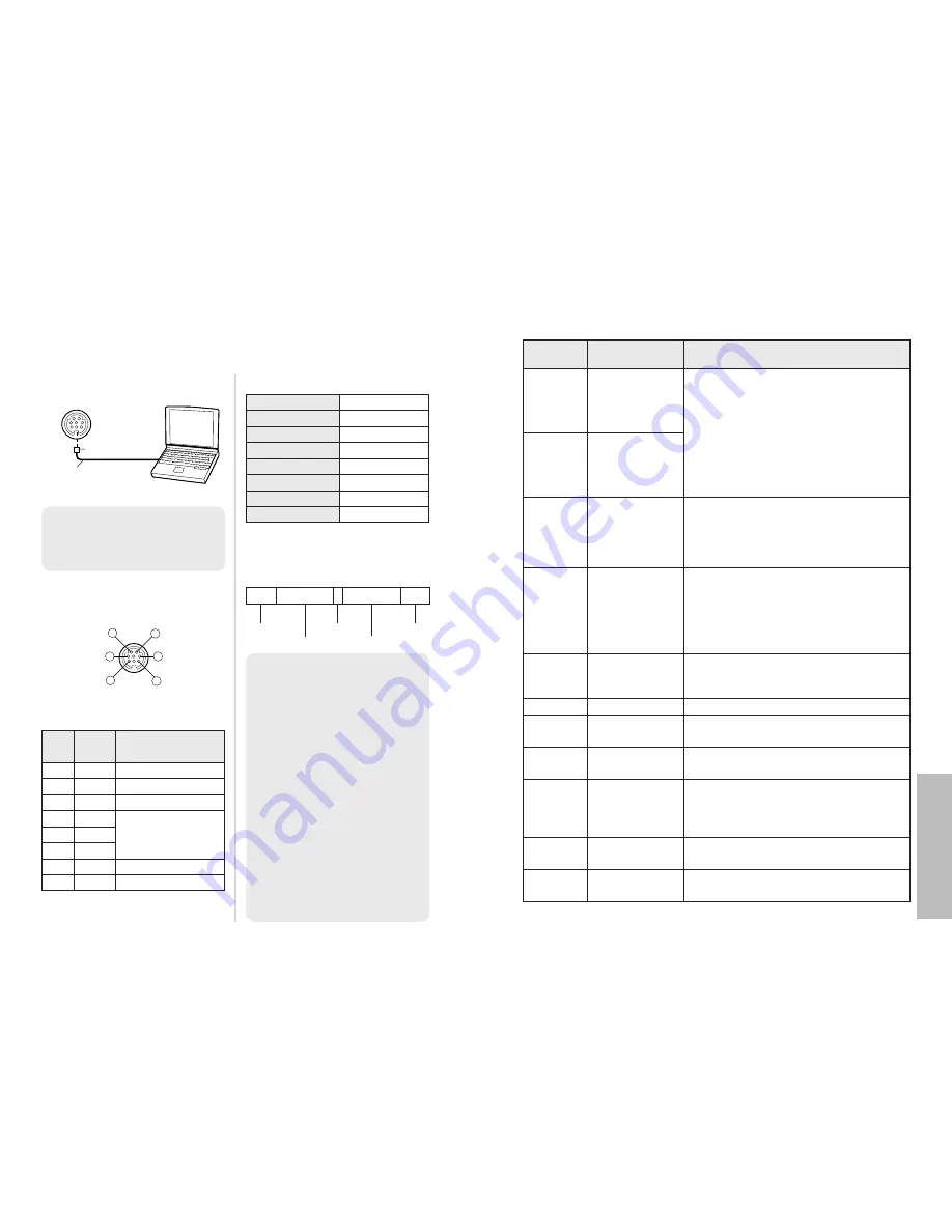
Using the SERIAL connector

The serial connector which is on the connector panel of the projector
conforms to the RS-232C interface specification, so that the projector can be
controlled by a personal computer which is connected to this connector.

Connection

Pin assignments and signal
names

Basic format

The data sent from the computer to
the projector is transmitted in the
format shown below.

Pin
No.

Communications settings

Signal

name

Contents

1

2

6

8

5

3

%

RXD

Received data

&

GND

Earth

'

TXD

Transmitted data

#
$

Connected internally

(
)
*

DIN 8-pin 

Appearance

Signal level

RS-232C

Asynchronous

Sync. method

Baud rate

Parity

9 600 bps

None

Character length 8 bits

Stop bit

1 bit

X parameter

None

S parameter

None

STX Command : Parameter ETX

Start byte
(02h)

3 bytes

1 byte

1 byte-4 bytes

End byte

(03h)

DIN 8-pin (male)

Serial adapter
(ET-ADSER : sold
separately)

SERIAL(female)

Computer

NOTE:

B

The projector can not receive
the command for 10 seconds
after the lamp is switched on.
Wait 10 seconds before sending
the command.

B

If sending multiple commands,
check that a response has been
received from the projector for
one command before sending
the next command.

B

When a command which does
not require parameters is sent,
the colon (:) is not required.

B

If an incorrect command is sent
from the personal computer, the
“ER401” command will be sent
from the projector to the
personal computer.

NC

NC

Control commands

Command Control contents

Remarks

In standby mode, all commands other than
the PON command are ignored.

B

The PON command is ignored during
lamp ON control.

B

If a PON command is received while the
cooling fan is operating after the lamp
has switched off, the lamp is not turned
back on again straight away, in order to
protect the lamp.

Power ON

PON

Power OFF

POF

Input signal
selection

IIS

Parameter
VID=VIDEO

SVD=S-VIDEO

RG1=PC YUV=YP

B

P

R

1

HDM=HDMI

CP1=YP

B

P

R

1

CP2=YP

B

P

R

2

Shutter function

OSH

Use this command to momentarily turn off
the picture.
Operation will be switched between ON and
OFF each time the command is sent. Do
not switch operation ON and OFF after only
short periods of time.

Freeze function

OFZ

The picture being projected will be paused.
Parameter
0=OFF

1=ON

F

G

I

and 

H

buttons

OCU
OCD

OCL

OCR

OCU= 

button

OCD= 

button

OCL= 

button

OCR= 

button

Menu screen

OMN

The menu screen will be displayed.

ENTER

OEN

Use this command to accept and to activate
items selected in the on-screen menus.

RETURN

OBK

Use this command to return to a previous
menu screen or to clear the menu screen.

MAIN

OVM

Use this command to display an item in the
“PICTURE” menu. (page 35)

Aspect ratio
selection

VS1

The aspect ratio will be switched each time
the command is sent. (page 30)

NOTE:

B

You must use only RS-232C
Serial Interface Cable with
ferrite core, type ET-ADSER.

(Continued on next page.)

Summary of Contents for PT-AE900U

Page 1: ...please read the instructions carefully and save this manual for future use For assistance please call 1 888 View PTV 843 9788 or send e mail to consumerproducts panasonic com or visit us at www panasonic com U S A For assistance please call 787 750 4300 or visit us at www panasonic co jp global Puerto Rico ...

Page 2: ...e grounding pin on the power plug This plug will only fit a grounding type power outlet This is a safety feature If you are unable to insert the plug into the outlet contact an electrician Do not defeat the purpose of the grounding plug WARNING This equipment has been tested and found to comply with the limits for a Class B digital device pursuant to Part 15 of the FCC Rules These limits are desig...

Page 3: ... Adjusting the position 48 Horizontal position Vertical position DOT CLOCK CLOCK PHASE ASPECT WSS OVER SCAN KEYSTONE AUTO SETUP Changing the display language 50 Option settings 51 OSD OSD DESIGN OSD POSITION AUTO SEARCH BACK COLOR STARTUP LOGO DESK CEILING FRONT REAR OFF TIMER FAN CONTROL LAMP POWER LAMP RUNTIME Care and maintenance When the TEMP indicator and the LAMP indicator are illuminated 54...

Page 4: ...riod of time pull the power cord plug out from the wall outlet Do not do anything that might damage the power cord or the power cord plug BDo not damage the power cord make any modifications to it place it near any hot objects bend it excessively twist it pull it place heavy objects on top of it or wrap it into a bundle BIf the power cord is used while damaged electric shocks short circuits or fir...

Page 5: ...smoke or steam BUsing the projector under such conditions may result in fire or electric shocks When disconnecting the power cord hold the plug not the cord BIf the power cord itself is pulled the cord will become damaged and fire short circuits or serious electric shocks may result Always disconnect all cables before moving the projector BMoving the projector with cables still attached can damage...

Page 6: ...fied technician to carry out all installation work You will need to purchase the separate installation kit Model No ET PKE300 ET PKE700 Furthermore all installation work should only be carried out by a qualified technician If using this projector at high elevations above 1 400 m set the FAN CONTROL to HIGH Refer to page 53 Failure to observe this may result in malfunctions NOTICE BThis product has...

Page 7: ...ently turned on and off Liquid crystal panel BDo not project the same image for long periods of time as this may remain as an afterimage on the liquid crystal panel BThe liquid crystal panel of the projector is built with very high precision technology to provide fine picture details Occasionally a few non active pixels may appear on the screen as fixed points of blue green or red Please note that...

Page 8: ...m an S VIDEO compatible equipment such as a video deck VIDEO IN connector page 22 This connector is used to input video signals from a video equipment such as a video deck COMPONENT 2 IN YPBPR CBCR input connectors page 22 These connectors are used to input YPBPR signals from compatible equipment such as a DVD player Connector panel page 15 Air inlet port Do not cover this port Power input socket ...

Page 9: ... SHUTTER button page 34 This button is used to momentarily turn off the picture 0MEM LOAD MEMORY LOAD button page 34 This button is used to display the MEMORY LOAD menu 1C C M Cinema Color Management button page 36 This button is used to display the COLOR MANAGEMENT menu 2ADVANCED button pages 35 and 46 This button is used to display an item from the ADVANCED MENU 3MAIN button pages 35 and 44 This...

Page 10: ...jector BIt is recommended that you set up the projector in a place that is tilted at less than 30 vertically Setting up the projector in places that are tilted at more than 30 vertically may shorten component life 18 ENGLISH Projector position L Projection distance SH Image height SW Image width Screen 1 01 m 40 0 50 m 1 7 0 89 m 2 11 1 2 m 3 11 2 4 m 7 10 1 27 m 50 0 62 m 2 1 11 m 3 7 1 5 m 4 11 ...

Page 11: ... is tilted vertically and keystone correction needs to be carried out place the projector so that the center of the lens and the center of the screen vertical are matched BProjector setting up range in relation to the screen Projector Screen Projector set up range center of the lens BHorizontal lens shift About 25 of the screen maximum About 25 of the screen maximum When shift lever is moved to th...

Page 12: ...s necessary for connection are not included with the peripheral device or available as an option you may need to prepare a proper cable for the device concerned BRefer to the list on page 64 for details on compatible signals which can be input to the projector BAn audio system circuit is not provided with this projector Connect the audio output of the connected equipment to a separate audio system...

Page 13: ...nit and the receptor the remote control unit may not operate correctly BIf strong light is allowed to shine onto the remote control signal receptor correct projector operation may not be possible Place the projector as far away from light sources as possible BIf facing the remote control unit toward the screen to operate the projector the operating range of the remote control unit will be limited ...

Page 14: ...startup logo not to be displayed set STARTUP LOGO to OFF Refer to page 52 Turn on the power of all connected devices BStart the play function of a device such as a DVD player NOTE BA rattling sound may be heard when the power is turned on and a tinkling sound may be heard when the lamp unit is turned on but these are not signs of malfunctions Power indicator 26 ENGLISH Adjusting the size BTurn the...

Page 15: ...he picture will stop being projected The power indicator on the projector will illuminate orange while the cooling fan is still operating Press the MAIN POWER switch to turn off the power after the power indicator on the projector illuminates red BDo not cut power to the projector in any way while the cooling fan is still operating Be careful not to switch off the MAIN POWER switch of the projecto...

Page 16: ...spect ratio H FIT 1 125 1 080 60i 1 125 1 080 50i 1 125 1 080 24p 750 720 60p and 750 720 50p signals only Horizontal expansion of projected image JUST Horizontal expansion of projected image Center of image is less distorted ZOOM ZOOM1 ZOOM2 ZOOM2 is for 2 35 1 letterbox signals Expansion preserves original ratio V SCROLL XGA MXGA SXGA WIDE768 only A picture is projected without expansion or redu...

Page 17: ...s not match the aspect ratio of the input signal it may affect the quality of viewing of the original picture BIf using this projector in places such as cafes or hotels to display programs for a commercial purpose or for public presentation note that if the aspect ratio selection function is used to change the aspect ratio of the screen picture you may be infringing the rights of the original copy...

Page 18: ...and the buttons to operate the selected device on the remote control unit Refer to page 17 for details Press the SHUTTER button Displaying the PICTURE menu MAIN Press the MAIN button BThe individual adjustment screen will be displayed as shown above Press the F or G button to switch the item BPress the I or H button to adjust the value or change the setting BYou can adjust PICTURE menu items using...

Page 19: ...picture mode being selected does not match the picture mode which had been selected when that profile was saved You can only check the color setting in the LOG menu B LOG and PROFILE SAVE are displayed only when the colors have been adjusted in CURSOR menu Using the Cinema Color Management function C C M You can adjust save and retrieve the settings for the selected colors of the projected image b...

Page 20: ...pressed Select OK to delete the settings Press the F or G button to select the setting you want to adjust and then press the ENTER button to display the selection screen To delete all the settings select ALL DELETE and then press the ENTER button The confirmation screen will then be displayed Select OK and then press the ENTER button All the settings in the LOG menu will be deleted and the PROFILE...

Page 21: ... VIDEO VIDEO signal is being input When a YPBPR PC HDMI signal is being input LANGUAGE menu page 50 OPTION menu page 51 BPress the MENU button to display the menu screen Refer to page 42 for details on how to operate the on screen menus POSITION menu page 48 When an S VIDEO VIDEO signal is being input When a PC signal is being input When a YPBPR signal is being input When a HDMI signal is being in...

Page 22: ...play does not appear and the item or function will not work even if the ENTER button is pressed Returning a setting to the factory default If you press the NORMAL button on the remote control unit you can return settings to the factory default settings However the operation of this function varies depending on which screen is being displayed B BWhen a menu screen is being displayed All the items o...

Page 23: ...I only The color is too deep I button The color is too pale H button TINT NTSC NTSC 4 43 YPBPR PC HDMI only This adjusts the flesh tones in the picture The flesh tones are greenish I button The flesh tones are reddish H button SHARPNESS To soften the picture details I button To sharpen the picture details H button COLOR TEMP White areas are bluish I button White areas are reddish H button DYNAMIC ...

Page 24: ...utton to select OK and then press the ENTER button The current picture setting will be saved MEMORY LOAD Press the ENTER button to display the MEMORY LOAD menu If any setting is not saved in the MEMORY SAVE menu the MEMORY LOAD menu will not be displayed Refer to page 34 on how to retrieve the saved settings SIGNAL MODE PC YPBPR HDMI only This displays the type of signal which is currently being p...

Page 25: ... ratio will also be switched automatically OFF WSS will not be detected from PAL or 625i 576i YPBPR signals OVER SCAN 525p 480p 625p 576p 1 125 1 080 60i 1 125 1 080 50i 1 125 1 080 24p 750 720 60p and 750 720 50p signals for YPBPR and HDMI signals only Set to OFF when some letters or parts of a projected image not visible around the edges of the image KEYSTONE When either the projector or the scr...

Page 26: ...o not want the signal name to be displayed Press the MENU button to display the menu screen Select the OPTION menu from the main menu and then press the ENTER button Press the F or G button to select an item Press the I or H button to change the setting OSD DESIGN You can select the background for the OSD from 3 types TYPE1 Transparent black TYPE2 Solid blue TYPE3 Transparent navy blue OSD POSITIO...

Page 27: ...creen REAR When using a translucent screen OFF TIMER The projector will return to standby mode after the duration of the period you set has passed The period can be set from 60 minutes to 240 minutes in 30 minute intervals The remaining time will be displayed 3 minutes before the projector returns to standby mode The setting will be cancelled if set to OFF before reaching the duration of the perio...

Page 28: ...the necessary repairs can be made When the TEMP indicator and the LAMP indicator are illuminated There are two indicators on the control panel of the projector which give information about the operating condition of the projector These indicators illuminate or flash to warn you about problems that have occurred inside the projector so if you notice that one of the indicators is on turn off the pow...

Page 29: ...very hot and touching it can cause burns Notes on replacing the lamp unit BThe light generating lamp is made of glass so dropping it or allowing it to hit hard objects may cause it to burst Be careful when handling the lamp BDispose of the removed old lamp with the same care that would be taken with a fluorescent light BA Phillips screwdriver is necessary for removing the lamp unit Lamp unit repla...

Page 30: ...ower on page 28 and then disconnect the power cord plug from the wall outlet and check that the area around the lamp unit has cooled down Use a Phillips screwdriver to turn the lamp unit cover fixing screws at the bottom of the projector and then remove the lamp unit cover Use a Phillips screwdriver to loosen the two lamp unit fixing screws until the screws turn freely Then hold the handle of the ...

Page 31: ...ing points Problem Possible cause Page Power does not turn on No picture appears The picture is fuzzy The color is pale or grayish The remote control unit does not operate The picture does not display correctly BThe power cord may not be connected BThe MAIN POWER switch is turned off BThe main power supply is not being supplied to the wall outlet BTEMP indicator is illuminated or flashing BLAMP in...

Page 32: ...DEO IN Single line RCA pin jack 1 0 V p p 75 Ω PC IN RGB Single line D sub HD 15 pin female R G B 0 7 V p p 75 Ω G SYNC 1 0 V p p 75 Ω HD SYNC TTL high impedance automatic positive negative polarity compatible VD TTL high impedance automatic positive negative polarity compatible COMPONENT IN Y PB CB PR CR Dual line RCA pin jack x 3 Y 1 0 V p p Including sync 75 Ω PB PR CB CR 0 7 V p p 75 Ω HDMI IN...

Page 33: ... 3 A PC 1 072 x 600 37 3 59 9 51 4 A PC 1 280 x 720 45 1 60 1 76 5 AA PC 1 024 x 768 48 4 60 0 65 0 A PC 1 024 x 768 56 5 70 1 75 0 A PC 1 024 x 768 60 0 75 0 78 8 A PC 1 024 x 768 68 7 85 0 94 5 A PC 1 024 x 768 72 1 89 0 99 2 A PC 1 280 x 768 45 3 56 5 76 2 A PC 1 152 x 864 64 0 71 2 94 2 A PC 1 152 x 864 67 5 74 9 108 0 A PC 1 280 x 1 024 64 0 60 0 108 0 A PC 1 360 x 768 48 8 59 8 73 8 A PC Dis...

Page 34: ...he personal computer the ER401 command will be sent from the projector to the personal computer NC NC Control commands Command Control contents Remarks In standby mode all commands other than the PON command are ignored BThe PON command is ignored during lamp ON control BIf a PON command is received while the cooling fan is operating after the lamp has switched off the lamp is not turned back on a...

Page 35: ...cifications Command Inquiry contents Parameter 000 OFF 001 ON VID VIDEO SVD S VIDEO RG1 PC YUV YPBPR1 HDM HDMI CP1 YPBPR1 CP2 YPBPR2 Power condition QPW Input signal QIN Picture mode QPM NAT NATURAL NOR NORMAL DYN DYNAMIC CN1 CINEMA1 CN2 CINEMA2 CN3 CINEMA3 VID VIDEO Refer to page 33 for details Shutter function QSH 0 OFF 1 ON Freeze function QFZ 0 OFF 1 ON Inquiry commands 54 2 1 8 335 13 3 16 82...

Page 36: ... Interface are trademarks or registered trademarks of HDMI Licensing LLC BThe font used in the on screen displays is a Ricoh bitmap font which is manufactured and sold by Ricoh Company Ltd All other trademarks are the property of the various trademark owners Information on Disposal in other Countries outside the European Union This symbol is only valid in the European Union If you wish to discard ...

Reviews: