66
AHU Kit – Installation Instructions –
11/2021
Electrical Wiring
5
5.3 Terminal board layout
5.3.1 MAH2/PAH2 models
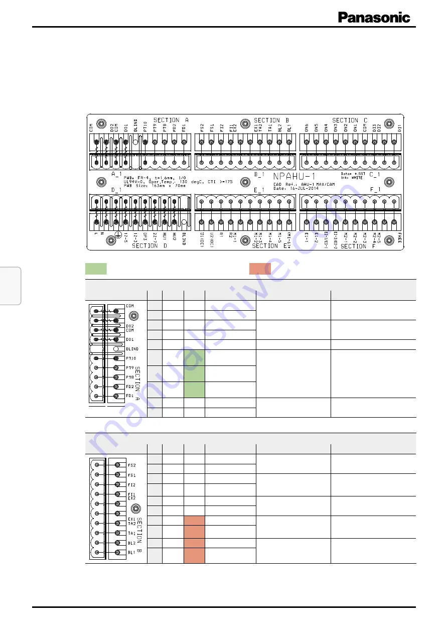
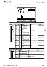
Terminal layout – Main terminal board (CR-UXRP71B-P)
= Input or Output necessary to connect.
= Input or Output can be connected if required.
Section A
Connections
No.
Name
In / Out
Allocation
Function
Description
10 COM
O
Alarm Signal
Alarm Signal
External Potential:
max. 230 V AC / 3 A
9 DO2
O
Alarm Signal
8 COM
O
Operation Signal
Operation Signal
External Potential:
max. 230 V AC / 3 A
7 D01
O
Operation Signal
6 Blind
Unused
5 PT10
I / O
Advanced:
Red
wire /
Medium:
White
wire
Advanced version: Connection of
PT-100 temperature sensor of thermo-
stat TR-16/TR-16e
Medium version: Connection of
analogue output temp. signal
Take care of wiring colours!
Note
: For advanced version connect only,
in case thermostat TR-16/TR-16e is being
used.
For medium version: PT10 = negative pole
(“–”) and PT9 = positive pole (“+”)
4 PT9
I / O
Advanced:
Red
wire /
Medium
Red
wire
3 PT8
I
Advanced:
White
wire /
Medium: not used
2 FD2
O
Fan Signal
Control of an additional external fan or
additional external air handling unit
Internal potential: 12 V DC
1 FD1
O
Potential for FD2
Section B
Connections
No.
Name
In / Out
Allocation
Function
Description
10 FS2
I
Float switch
Float switch
(ex factory bridged)
Internal Potential: 12 V DC
9 FS1
I
Potential for FS2
8 FI2
I
Filter contact
Filter contact
Internal Potential: 5 V DC
Note
: For activating filter input, verify in De-
tailed Settings that code 2A is set to “0000”
7 FI1
I
Potential for FI2
6 EX2
I
EXCT-Contact
EXCT-Contact
(external thermostat off switch)
Internal Potential: 5 V DC
5 EX1
I
Potential for EXCT
4 TA2
I
No polarity
Suction Temperature Sensor TA
(included)
(Room Temperature Sensor)
3 TA1
I
No polarity
2 BL2
I
No polarity
Discharge Temperature Sensor BL (in-
cluded only with PAW-xxxMAH2(L/M))
1 BL1
I
No polarity
To be continued on next page.
Summary of Contents for PAW-280PAH3M-1
Page 2: ...Notes ...
Page 113: ...Notes ...


