PAN1780 Bluetooth Module
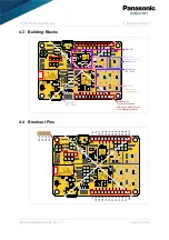
4 Reference Design
Module Integration Guide Rev. 1.1
Page 17 of 44
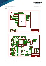
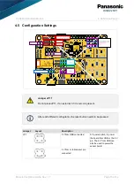
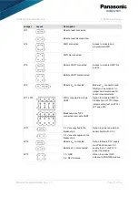
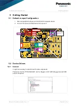
Jumper
Layout
Description
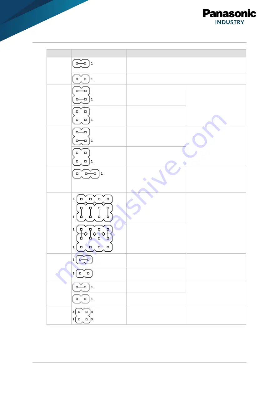
JP3
Module reset connected
Module reset disconnected
JP4
SWD connected
Access to module and
programmer SWD.
SWD disconnected
JP8
Module UART connected
Access to module UART Rx
and Tx.
Module UART disconnected
JP9
Module V
CC
connected
Module V
CC
connection and
GND pin. The module V
CC
jumper can be removed for
current measurements.
JP7, JP10
FTDI connected to module
UART
Option for module UART to
breakout pin or FTDI. Place
jumpers either just on JP7 or
JP7 and JP10.
Breakout pins of JP2
connected to module UART
JP11
3.3 V are supplied to the
breakout pin
Option to power an external
sensor board with 3.3 V.
3.3 V are not supplied to the
breakout pin
JP12
Module V
CC
connected
Option to break 3.3 V supply
via JP9 and connect 5 V
supply to pin 1 of JP12 to
power the module.
Module V
CC
not connected
JP13
1, 3: GND
2, 4: NFC Antenna
Option to connect NFC
antenna to PAN1780 module.

