


1-3
X-RADIATION
WARNING :
1. The potential source of X-Radiation in TV sets is the High Voltage section and the picture tube.
2. When using a picture tube test fixture for service, ensure that the fixture is capable of handling
25.0KV : Model
A,B,C,D,E,F,G
or
30.0KV : Model H,I,J,K
or
32.0KV : Model L
(see chart, Page 1-1) without causing X-Radiation.
NOTE :
It is important to use an accurate periodically calibrated high voltage meter.
1. Reduce the brightness to minimum.
2. Set the SERVICE switch to SERVICE .
3. Measure the High Voltage. The meter reading should indicate
23.5±1.5KV : Model A,B,C,D,E,F,G
or
28.5±1.5KV : Model
H,I,J,K
or
30.0±2.0KV : Model L
(see chart, Page 1-1).
If the meter indication is out of tolerance, immediate service and correction is required to prevent the possibility of premature
component failure.
4. To prevent an X-Radiation possibly, it is essential to use the specified picture tube.
HORIZONTAL OSCILLATOR DISABLE CIRCUIT TEST
SERVICE WARNING :
The test must be made as a final check before set is returned to the customer.
1. With the rear cover removed, supply about a 120V AC power source to the set, turn on the set.
2. Set the customer controls to normal operating positions.
3. Short between TP91 and TP92 on the Main circuit board with a jumper wire. Confirm that the picture goes out of horizontal sync.
4. If this does not occur, the horizontal oscillator disable circuit is not operating. Follow the Repair Procedures of horizontal oscillator
disable circuit before the set is returned to customer.
REPAIR PROCEDURES OF HORIZONTAL OSCILLATOR DISABLE CIRCUIT
1. Connect a DC voltmeter between capacitor C555 (+) on the Main circuit board and chassis ground.
2. If approxi21.9V is not present at that point when 120V AC is applied, find the cause. Check R515, R5505, R5507, C555
and D554.
3. Carefully check above specified parts and related circuits and parts. When the circuit is repaired, try the horizontal oscillator disable
circuit test again.
CIRCUIT EXPLANATION
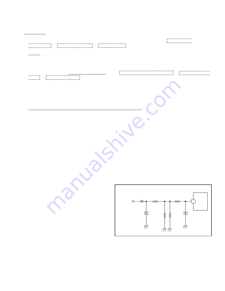
HORIZONTAL OSCILLATOR DISABLE CIRCUIT
The positive DC voltage, supplied from the D554 cathode for
monitoring high voltage, is applied to the IC5301 Pin11 through
R515 and R5504. Under normal conditions, the voltage at
IC5301 Pin11 is less than approx 3V. If the high voltage at
Flyback Tr Pin 5 exceeds the specified voltage, the positive
DC voltage which is supplied from the D554 cathode also
increases. The increased voltage is applied to IC5301 Pin11
through R515 and R5504. Due to the increased voltage at
IC5301 Pin11, the horizontal oscillator frequency increases,
the picture goes out of horizontal sync, the beam current
decreases and the picture becomes dark in order to keep X-
radiation under specification.
Figure 2
IC5301
11
+
-
+
-
R5505
R515
D554
C555
C5507
To Pin 5
of Flayback
Transformer
R5504
R516
(Model : L)
Summary of Contents for OmniVision PV-M1326
Page 42: ......
Page 43: ......
Page 44: ......
Page 45: ......
Page 46: ......
Page 47: ......
Page 48: ......
Page 49: ......
Page 50: ......
Page 51: ......
Page 52: ......
Page 53: ......
Page 54: ......
Page 55: ......
Page 56: ......
Page 57: ......
Page 58: ......
Page 59: ......
Page 60: ......
Page 61: ......
Page 62: ......
Page 63: ......
Page 64: ......
Page 65: ......
Page 66: ......
Page 67: ......
Page 68: ......
Page 69: ......
Page 70: ......
Page 71: ......
Page 72: ......
Page 73: ......
Page 74: ......
Page 75: ......
Page 76: ......
Page 77: ......
Page 78: ......
Page 79: ......
Page 80: ......
Page 81: ......
Page 82: ......
Page 83: ......
Page 84: ......
Page 85: ......
Page 86: ......
Page 87: ......
Page 88: ......
Page 89: ......
Page 90: ......
Page 91: ......
Page 92: ......
Page 93: ......
Page 94: ......
Page 95: ......
Page 96: ......
Page 97: ......
Page 98: ......
Page 99: ......
Page 100: ......
Page 101: ......
Page 102: ......
Page 103: ......
Page 104: ......
Page 105: ......
Page 106: ......
Page 140: ......
Page 141: ......
Page 142: ......
Page 143: ......
Page 144: ......
Page 145: ......
Page 146: ......
Page 147: ......
Page 148: ......
Page 149: ......
Page 150: ......
Page 151: ......
Page 152: ......
Page 153: ......
Page 154: ......
Page 155: ......
Page 156: ......
Page 157: ......
Page 158: ......
Page 159: ......
Page 160: ......
Page 161: ......
Page 162: ......
Page 163: ......
Page 164: ......
Page 165: ......
Page 166: ......
Page 167: ......
Page 168: ......
Page 169: ......
Page 170: ......
Page 171: ......
Page 172: ......
Page 173: ...Printed in Japan R...