background image

36

(The previously selected screen
appears on the left.)

Split screen

LIGHT

MUTE

TV/VIDEO

POWER

VCR

DVD

AUX

RCVR

DBS

TV

DTV

CBL

CH

SLOW

STILL

1

2

3

4

5

6

7

8

9

0

R-TUNE

PROG

AV-ADJ

NORMAL

GAME

RH-SPLIT

EXIT

VCR REC

GUIDE

REW

SEARCH

STOP

PLAY

VCR/DBS

CHANNEL

ACTION

VOL

VOL

CH

MENU

INFO/RECALL

ASPECT

OPEN/CLOSE

FREEZE

TV/VCR

SPLIT

FF

SWAP

PAUSE

TV/VIDEO

RH-SPLIT

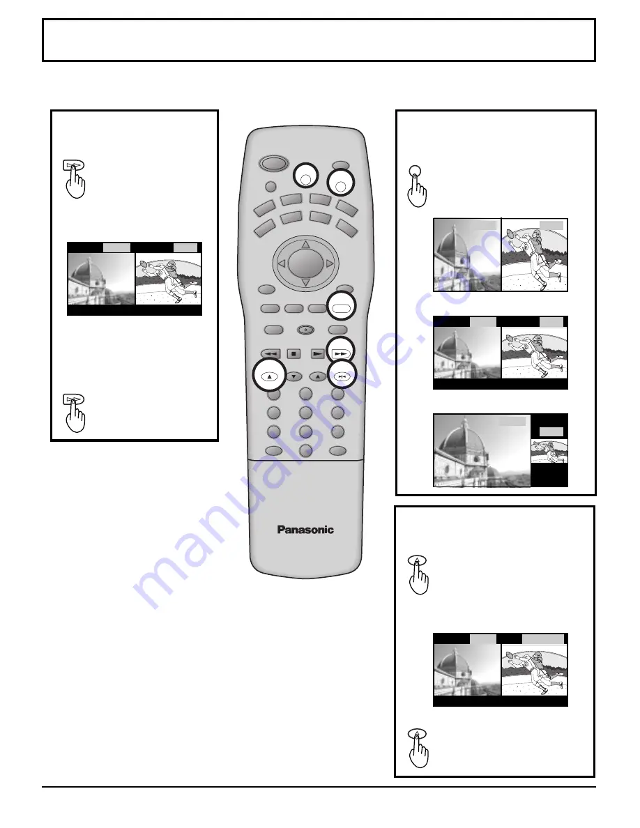
Split screen enables you to search other channels on the right screen or check video recording status.

Splitting the screen

SPLIT

FF

Press to split

Press to select modes.

(FULL)

Freezing pictures

FREEZE

TV/VCR

OPEN/CLOSE

Press during single screen to
freeze.
The screen is split and the
freeze image is displayed on
the right and the broadcast
channel continues on the left.

Press to return.

SPLIT

FF

FREEZE

TV/VCR

OPEN/CLOSE

Notes:

Split screen can be accessed during TV signal and Video1-4 input
modes, however, this does not apply when signal is input from
Component 1-3 and PC.

 Sound from the left screen is output from the speakers on the projection

TV set.

 When the screen is split, signals of the left screen are output from the

rear monitor output terminal.

 The left and right screen are processed by individual circuits and,

therefore, may have slight variation in sound and image quality.

 Split screen returns to single screen when the projection TV is turned

off.

ASPECT

 Returning to one screen.

Example: Two screen mode set

to NORMAL aspect.

Selecting the screen mode for
split screen.

(PoutP)

(NORMAL)

Press to recover.

CH3

CH10

CH3

CH10

CH3

CH10

CH10

CH3

FREEZE

CH10

Summary of Contents for OmniVision PV-DF2036M

Page 1: ...720p SPATIALIZ RT 3 D STEREO DLP TM ATEXAS INSTRUMENTS TECHNOLOGY HDTV COMPATIBLE 1080 i 720p SPATIALIZRT 3 D STEREO For assistance please call 1 888 VIEW PTV 843 9788 or send e mail to consumerproducts panasonic com or visit us at www panasonic com USA For assistance please call 787 750 4300 or visit us at www panasonic com Puerto Rico ...

Page 2: ... cart combination shall be moved with care Quick stops excessive force and uneven surfaces may cause the appliance and cart combination to overturn 8 Slots and openings in the cabinet and the back or bottom are provided for ventilation and to insure reliable operation of the projection TV and to protect it from overheating These openings must not be blocked or covered There shall be at least 10 cm...

Page 3: ...illed into the projection TV c If the projection TV has been exposed to rain or water d If the projection TV does not operate normally by follow the operating instructions Adjust only those controls that are covered by the operating instructions as improper adjustment of other controls may result in damage and will often require extensive work by a qualified technician to restore the projection TV...

Page 4: ...ed compliance and prevent undesirable interference use only the provided shielded VGA cable with 2 ferrite cores Part TSXF147 while connecting the Projection TV to a computer Any changes or modifications not expressly approved by the party responsible for compliance could void the user s authority to operate this equipment Pursuant to 47CFR Part 15 21 of the FCC rules any changes or modifications ...

Page 5: ...ming 24 Tuning channels Manual channel programming 26 ASPECT Controls 28 VHF UHF and CATV 30 Cable TV 31 Searching for the desired channel Channel search 32 Playing a VCR or other peripheral equipment 33 Playing games in game mode 34 Recall Mute 35 Split screen 36 Adjusting screen position and size 38 Audio Adjustments 40 Picture Adjustments 42 Playing special video software 45 Closed Captions 46 ...

Page 6: ...ding reflections will fall on the screen Use of some types of fluorescent lighting can reduce remote control transmitter range Adequate ventilation is essential to prevent internal component failure Keep away from areas of excessive heat or moisture Optional External Equipment AC Power Supply Cord CAUTION To prevent electric shock match wide blade of plug to wide slot of AC outlet and fully insert...

Page 7: ...th a new one 3 Do not mix battery types example Zinc Carbon with Alkaline 4 Do not attempt to charge short circuit disassemble heat or burn used batteries 5 Battery replacement is necessary when the remote control acts sporadically or stops operating the projection TV set Helpful Hint Whenever you remove the batteries you may need to reset the remote control infrared codes We recommend that you re...

Page 8: ...els A cable converter box is required for proper reception Check with your local Cable company for its compatibility requirements Connecting the Antenna Cable to the RF In Terminal TO AUDIO AMP L R AUDIO VIDEO S VIDEO L R AUDIO VIDEO L PR PB Y R INPUT ANT1 ANT2 SPLIT OUT COMPONENT VIDEO INPUT PROG OUT 2 1 3 2 1 3 ANT1 ANT2 SPLIT OUT UHF Antenna RF In Terminal VHF Antenna Mixer Coaxial Antenna Plug...

Page 9: ...IT OUT COMPONENT VIDEO INPUT PROG OUT 2 1 3 2 1 3 ANT1 ANT2 SPLIT OUT Installation ANTENNA TERMINALS ON THE BACK OF THE PROJECTION TV CABLE BOX INPUT OUTPUT TERMINAL ON THE BACK OF THE CABLE BOX Notes When the antenna cable is connected to the projection TV antenna terminal via a cable box or VCR set the TV channel to CH3 or CH4 cable after select ANT2 in the PROGRAM CHANNELS See page 24 26 This d...

Page 10: ...e back of the CABLE BOX OUTPUT S VIDEO VIDEO L AUDIO R TO AUDIO AMP L R AUDIO VIDEO S VIDEO L R AUDIO VIDEO L PR PB Y R INPUT ANT1 ANT2 SPLIT OUT COMPONENT VIDEO INPUT PROG OUT 2 1 3 2 1 3 ANT1 ANT2 SPLIT OUT Installation INPUT OUTPUT OUTPUT INPUT VCR Notes When the antenna cable is connected to the projection TV antenna terminal via a cable box or VCR set the TV channel to CH3 or CH4 cable after ...

Page 11: ...l and the video input terminal are connected at the same time How to connect the 1 2 3 4 Input Terminals Connects VCRs and other peripheral equipment TO AUDIO AMP L R AUDIO VIDEO S VIDEO L R INPUT PROG OUT 2 1 3 Super VHS VCR Audio OUT Video OUT S Video OUT R L VIDEO AUDIO TO AUDIO AMP L R AUDIO VIDEO S VIDEO L R INPUT PROG OUT 2 1 3 VHS VCR VIDEO AUDIO Audio OUT Video OUT R L Similar connections ...

Page 12: ... DVD Y PB PR OUT L R DVD Player Y PB PR AUDIO VIDEO L PR PB Y R COMPONENT VIDEO INPUT 2 1 3 How to connect the COMPONENT VIDEO Input Terminals Installation Note Similar connections are available at the COMPONENT VIDEO Input 1 2 3 Terminals ...

Page 13: ...s Notes Never connect the VIDEO IN and Prog OUT terminals to the same video recorder as this could cause incorrect operation The monitor output emits the main picture s normal video and audio signals Even if the television is in picture out picture condition Prog OUT terminals output the same signals as main picture on the screen and sound from speaker Sub picture including still channel search et...

Page 14: ...me dark if a PC signal with a vertical scanning frequency of 62 Hz is input To obtain the optimum picture quality with the projection TV a vertical scanning frequency of 60 Hz is recommended 8 Do not set the horizontal and vertical scanning frequencies for PC signals which are above or below the specified frequency range Signal Names for D SUB 15P Connector Pin Layout for PC Input Terminal Pin No ...

Page 15: ...dots other than 800 600 in the above data will be converted to 800 600 with the exception of MAC 16 which will be displayed in 832 624 dots Display mode name VGA400 VGA480 SVGA XGA MAC16 No of dots H V 640 400 640 400 640 480 640 480 640 480 640 480 640 480 800 600 800 600 800 600 800 600 800 600 800 600 1024 768 1024 768 1024 768 832 624 Horizontal scanning frequency kHz 24 8 31 5 31 5 35 0 37 9 ...

Page 16: ...election for Remote Control Aux Mode Selection for Remote Control TV Mode Selection for Remote Control Digital Broadcasting Satellite for Remote Control Receiver Amplifier Mode Selection for Remote Control Digital TV Mode Selection for Remote Control Cable TV Mode Selection for Remote Control Buttons TV VCR CABLE DBS DVD LD CD RCVR Split Freeze TV VCR switch Open Close Channel down Channel down Ce...

Page 17: ...annel down Moves cursor downward during menu mode Increase volume Moves cursor to the right during menu mode Changes to the next channel up Moves cursor upward during menu mode Lights the remote control buttons The selected button blinks when lit NORMAL JUST FULL ZOOM ASPECT button Change of screen size See page 28 PROG button The screen below is displayed for 10 seconds Returns to normal viewing ...

Page 18: ...tton see page 23 Menu button see page 22 Input4 terminals Video camera and TV game cable terminal Open Open PC Input terminal Press the mark on the center of the front cover to open FRONT Lamp unit see page 62 Speaker panel Remote Control Sensor see page 21 TEMP This indicator lights up when there is an abnormal temperature in the unit see page 71 LAMP This indicator lights up when there is a malf...

Page 19: ...IDEO INPUT PROG OUT 2 1 3 2 1 3 AUDIO VIDEO L PR PB Y R COMPONENT VIDEO INPUT 2 1 3 TO AUDIO AMP L R AUDIO VIDEO S VIDEO L R INPUT PROG OUT 2 1 3 Input1 terminals see page 11 Input2 terminals see page 13 Input3 terminals see page 13 Component signal input see page 12 REAR Monitor out terminals see page 13 ...

Page 20: ...n on the power again immediately after turning off the power during the operation of the projection TV be sure to wait until the cooling fan stops and then turn on the power Setting the projection TV to Stand by the power indicator will light up red Push the Power switch on the projection TV to turn the power on The Power Indicator will become Green and blink approximately 10 seconds Example The s...

Page 21: ... button to turn the projection TV to Stand by mode The Power Indicator will become Orange Approximately 90 seconds The Power Indicator will become Red POWER LED No illuminated Red Green Green blink Orange blink ACTION Power OFF Stand by Power ON Power ON approximately 10 seconds after Power OFF by the remote control approximately 90 seconds after Power ON OFF button STEREO SAP MONO NORMAL CH123 Th...

Page 22: ...EO MENU VOLUME CHANNEL Select MENU desired by pushing Right button or Left button The MENU button on the main body can also be pressed to display the MENU screen 1 2 MENU CH VOL VOL CH ACTION The Right button and Left button on the main body can also be used to select items on the MENU screen MENU ADJUST CUSTOM PICTURE AUDIO SELECT SET UP EXIT PAGE ACTION PICTURE ADJUST POSITION SIZE CLOCK AUDIO A...

Page 23: ...CT AUDIO MENU BASS TREBLE BALANCE SPATIALIZER SPEAKERS EXIT CHANGE 6 4 0 SLEEP TIMER 0 SLEEP TIMER EXIT CHANGE AUDIO MODE EXIT CHANGE AUDIO MODE STEREO SAP MONO PROGRAM CHANNELS SELECT EXIT CHANGE MODE TV CABLE ANTENNA ANT1 ANT2 AUTO PROGRAM MANUAL PROGRAM V I D E O PAGE 2 3 SELECT EXIT CHANGE OFF ON OFF ON TV GAME 3D Y C FILTER ID 1 SCAN MODE V I D E O PAGE 3 3 SELECT EXIT CHANGE GAME 480p COLOR ...

Page 24: ...ANNELS CH VOL VOL CH ACTION Press to select MODE CH VOL VOL CH ACTION Press to select ANT1 or ANT2 Press to select ANTENNA PROGRAM CHANNELS SELECT EXIT CHANGE MODE TV CABLE ANTENNA ANT1 ANT2 AUTO PROGRAM MANUAL PROGRAM 4 Press to select AUTO PROGRAM AUTO PROGRAM Activate AUTO PROGRAM NO EXIT ACTION YES CHANGE CH VOL VOL CH ACTION Press to display the confirmation screen Note TV or Cable Tuning mod...

Page 25: ... mode Some channels with very weak signals may be locked into memory It desired these channels can be deleted manually using the Manual Program feature Tuning channels Automatic channel programming 5 Press to select YES Channels will automatically advance until all channels have been scanned Channel numbers with a video signal present will turn blue which indicates stored in the Channel Scan Memor...

Page 26: ...G R A M CHANNELS Press the MENU button to display the MENU screen and select SETUP 4 MANUAL PROGRAM ENTER CHANNEL 122 EXIT DELETE CH SELECT or number key ADD CH VOL VOL CH ACTION Press to display the PROGRAM CHANNELS CH VOL VOL CH ACTION Press to select TV or CABLE CH VOL VOL CH ACTION Press to display the MANUAL P R O G R A M screen 3 CH VOL VOL CH ACTION Press to select ANT1 or ANT2 Press to sel...

Page 27: ...annels CH VOL VOL CH ACTION CH VOL VOL CH ACTION Press to delete channels from memory yellow Press to select channel Press to exit menu MENU Notes PROGRAM CHANNELS are valid only during TV mode Some channels with very weak signals may be locked into memory It desired these channels can be deleted manually using the Manual Program feature MANUAL PROGRAM ENTER CHANNEL 122 EXIT DELETE CH SELECT or nu...

Page 28: ... FREEZE TV VCR SWAP PAUSE VCR DBS CHANNEL ACTION VOL VOL CH MENU INFO RECALL ASPECT ASPECT button The aspect mode changes each time the ASPECT button is pressed Notes For a 480p signal input during component input signal mode the mode switches ZOOM and FULL only When a 1080i and 720p signal is being received the mode is set to FULL and aspect switching is not possible During PC mode the mode switc...

Page 29: ...at elongation is only apparent at the left and right edges of the screen The size of the picture will depend on the original signal Notes The S VIDEO terminal on this set can detect specially encoded signals that are compatible with a wide screen monitor When a full image from the S VIDEO terminal of specially encoded video is detected by the set the screen size is automatically set to FULL mode T...

Page 30: ... REC GUIDE REW SEARCH STOP PLAY SPLIT FF FREEZE TV VCR SWAP PAUSE VCR DBS CHANNEL VOL VOL MENU INFO RECALL CH ACTION CH POWER TV Press to turn the projection TV on see page 21 Press to operate the projection TV with the remote control Press to select the desired channel Press to select the desired volume level 1 2 3 4 POWER TV Notes The channel number and volume level are stored even after the pro...

Page 31: ...Note The remote control code number is set for Panasonic products When peripheral equipment do not operate reset code see page 63 64 Operate the cable TV tuner and select the desired volume level CBL POWER TO AUDIO AMP L R AUDIO VIDEO S VIDEO L R AUDIO VIDEO L PR PB Y R INPUT ANT1 ANT2 SPLIT OUT COMPONENT VIDEO INPUT PROG OUT 2 1 3 2 1 3 ANT1 ANT2 SPLIT OUT ANTENNA TERMINALS ON THE BACK OF THE PRO...

Page 32: ...e right screen Freeze is deactivated Sound from the left screen is output from the speakers on the projection TV set 1 4 6 2 5 7 When the SEARCH button is pressed during screen PoutP or pause SEARCH STOP SEARCH STOP Ex Select channel 7 Ex Select channel 7 LIGHT MUTE TV VIDEO POWER VCR DVD AUX RCVR DBS TV DTV CBL CH SLOW STILL 1 2 3 4 5 6 7 8 9 0 R TUNE PROG AV ADJ NORMAL GAME RH SPLIT EXIT VCR REC...

Page 33: ... 2 No input mode is displayed for terminals with no signal Turning the power on and switching input modes This equipment can also be connected to the rear terminals See Connections for details Notes When the remote control is unavailable input modes can also be switched on the projection TV set using the TV VIDEO button Component 1 3 and PC is displayed during single screen but is not displayed du...

Page 34: ...ing the Video Input 4 terminal on the front of the projection TV To S video output or video output To audio output Turning on the projection TV and switching to game modes Video game player TV screen Displays the lapsed time Lapsed time is displayed for 5 seconds every 30 minutes Be sure to rest your eyes every 30 minutes GAME 30 GAME 60 GAME 90 The lapsed time display stops after 90 minutes Notes...

Page 35: ... a specified period Press this button again to delete channel number display INFO RECALL Recall On screen display Useful when answering the phone or receiving unexpected visitors MUTE Mute Press this button to mute the sound Press again to reactivate sound Sound is also reactivated when power is turned off or volume level is changed Full Information Channel No display SLEEP TIMER 30 STEREO SAP MON...

Page 36: ...s displayed on the right and the broadcast channel continues on the left Press to return SPLIT FF FREEZE TV VCR OPEN CLOSE Notes Split screen can be accessed during TV signal and Video1 4 input modes however this does not apply when signal is input from Component 1 3 and PC Sound from the left screen is output from the speakers on the projection TV set When the screen is split signals of the left ...

Page 37: ... ACTIVE is displayed the left screen will not operate Swapping left and right screens During SPLIT SCREEN FULL SPLIT SCREEN NORMAL PoutP Press to swap Example During SPLIT SCREEN NORMAL Notes The right and left screens cannot display the same picture at the same time Use the right screen when playing video games on a split screen to avoid distortion of images When the ANTENNA setting is set to ANT...

Page 38: ...played on a wide screen TV will be cut off or distorted at the edges when viewing normal aspect images of 4 3 in ZOOM JUST or FULL mode Display in NORMAL mode to view the original image intended by the producer For 1080i 720p and 480p input images screen position and size cannot be adjusted The adjusted setting will be kept even when the projection TV is turned off The signals output from the moni...

Page 39: ...eturn to NORMAL ACTION To end ADJUSTMENTS MENU EXIT Press to enlarge image vertically max 15 Displaying images cut off from the screen For ZOOM mode Press to move image upwards Adjusting screen position and size CH VOL VOL CH ACTION CH VOL VOL CH ACTION CH VOL VOL CH ACTION CH VOL VOL CH ACTION Press to widen SIZE 1 Press to shrink image horizontally SIZE 1 Press to shrink image vertically min 1 P...

Page 40: ...ct AUDIO ADJUST STANDARD DYNAMIC MUSIC 1 MUSIC 2 AUTO SPATIALIZER To enjoy a concert hall effect turn SPATIALIZER to ON During stereo sound or soft playing During monaural sound OFF ON SPATIALIZER SPATIALIZER OFF ON BASS Adjusts low sounds TREBLE Adjusts high sounds BALANCE Adjust left and right volumes To reset to NORMAL setting select NORMALIZE with the up and down buttons and press ACTION NORMA...

Page 41: ...N and OFF SPEAKERS OFF Turns off the speaker sound SPEAKERS ON Speaker sound is normal OFF ON SPEAKERS OFF ON SPEAKERS Audio Adjustments To end adjustments Press MENU button MENU Notes Sound signals are output from the rear AUDIO OUT terminal When volume is adjusted or the mute button is pressed from the remote control a message will displayed ...

Page 42: ...ect to PICTURE ADJUST Press when PICTUREADJUST screen is displayed NORMAL is displayed at default When setting are altered changes to NORMALIZE STANDARD CINEMA DYNAMIC NORMAL COOL WARM STANDARD CINEMA DYNAMIC STANDARD Displays unaltered image CINEMA Ideal for movies DYNAMIC Displays a clear screen with contrast of light and dark Press to select the menu to adjust Press the left or right button to ...

Page 43: ...ected for the PICTURE MENU Note There is little change when PICTURE is increased with a bright picture or reduced with a dark picture To adjust each item Press the up and down button and make adjustments using the left and right buttons Select NORMALIZE with the up and down buttons and press ACTION By pressing the AV ADJ button on the remote control PICTURE ADJUST and AUDIO ADJUST can be directly ...

Page 44: ...ng from the MAIN menu The selected menu will change each time the AV ADJ button is pressed press till the desired menu is displayed NORMAL PICTURE BRIGHTNESS COLOR TINT SHARPNESS COLOR TEMP 15 0 0 0 0 OFF ON BASS TREBLE BALANCE SPATIALIZER 6 4 0 CH VOL VOL CH ACTION AV ADJ Adjust using the left or right button Picture Adjustments ...

Page 45: ...e players use GAME mode Use TV mode for normal viewing Selecting VIDEO menu Press the MENU button to display the MENU screen and select SETUP Switching to SCAN MODE Press to select SCAN MODE Press to select TV or GAME Note The VIDEO set up screen is made up of 3 pages Use the up and down buttons to change pages Press to select VIDEO 1 2 Press to exit menu V I D E O PAGE 1 3 SELECT EXIT CHANGE OFF ...

Page 46: ... button on the Remote Control is pressed To deactivate press the MUTE button again NO ON MUTE NO OFF C1 C2 C3 C4 Notes Recommended menu Set Up for Closed Caption when using Mute Button CC ON MUTE C1 CC MODE OFF The setting for CC ON MUTE is valid only when the CC MODE is OFF CC MODE set to ON will override CC ON MUTE This menu cannot be selected when the MAIN picture is displaying a COMPONENT VIDE...

Page 47: ...any other information currently being transmitted Another mode which displays information and blanks out a large portion of the picture on the television screen Another mode used for video related information Another mode used for video related information Another mode which displays information and blanks out a large portion of the picture on the television screen Another mode which displays info...

Page 48: ...ams Their function is to block programs by the rating data in the XDS data packets sent from broadcasting stations The user can select which rating programs should be blocked by the LOCK MENU options 2 Press to select CHANGE SETTING the menu following MOTION PICT STATUS Input code Enter any 4 digit number as a password These numbers will be needed when deactivating the LOCK function Selecting broa...

Page 49: ...ngs selected above Press to set MOTION PICTURE RATING VIEW NR PROGRAMS NO YES G PG PG 13 R NC17 X RATING NO RATING SELECT EXIT Lock Feature OFF ON MOTION PICT STATUS CH VOL VOL CH ACTION CH VOL VOL CH ACTION CH VOL VOL CH ACTION MENU Rating turns red when on G General audience PG Parental guidance suggested PG 13 Parental guidance needed under 13 years old R Restricted NC17 No one under 17 is admi...

Page 50: ...TATUS TV PARENTAL STATUS CHANGE CODE CHANGE SETTING CHANGE SETTING SELECT EXIT CHANGE TV PARENTAL GUIDE VIEW NR PROGRAMS SETTING DETAILED NO YES FV V V V S S S L L L D D RATING NO RATING SELECT EXIT TV Y TV Y7 TV G TV PG TV 14 TV MA Changing setting Press to select CHANGE SETTING Setting the TV PARENTAL PROGRAMS screen VIEW NR PROGRAMS NO Cannot view programs with NR signals YES Can view programs ...

Page 51: ...PUT labels Press to select VIDEO Display for each VIDEO INPUT can be changed to match with the connected device VCR video games 1 2 Example When changing VIDEO 3 to LD Note The VIDEO screen consists of 3 pages Use the up and down buttons to change pages Press to select VIDEO INPUT LABEL V I D E O PAGE 1 3 SELECT EXIT CHANGE OFF ON NORMAL FRAME VIDEO NR DVC PLAYBACK MODE CH VOL VOL CH ACTION CH VOL...

Page 52: ...ut signal 3 By pressing this button display changes as follows Press to exit menu Press to select VIDEO INPUT to change VIDEO INPUT LABEL VIDEO 1 VIDEO 2 VIDEO 3 VIDEO 4 COMPONENT 1 COMPONENT 2 COMPONENT 3 VIDEO 1 VIDEO 2 VIDEO 3 VIDEO 4 COMPONENT 1 COMPONENT 2 COMPONENT 3 SELECT EXIT CHANGE VIDEO 3 VCR LD GAME BLANK HD VCR DTV DVD Customizing the VIDEO INPUT labels CH VOL VOL CH ACTION CH VOL VOL...

Page 53: ...IO MODE STEREO SAP MONO STEREO Two channel Audio reception SAP Second Audio Programming typically used for bilingual audio MONO Use when stereo signal is weak Helpful Hints Mode Stereo SAP Mono When Audio is broadcast in Stereo or SAP an ON Screen display will appear on initial Turn On and Channel Change The available choices will be indicated in Green Press to exit menu Red display With signal Wh...

Page 54: ...ME TIME overrides the remaining Sleep Time The remaining Sleep Time will blink onscreen while less than 3 minutes even without pressing the recall button Press the left or right button and select the desired sleep time from 0 30 60 90 minutes to select times CH VOL VOL CH ACTION MENU ADJUST CUSTOM CHANNEL SEARCH SLEEP TIMER 0 AUDIO MODE SELECT SET UP EXIT PAGE ACTION CH VOL VOL CH ACTION SLEEP TIM...

Page 55: ... Default is set for VIDEO INPUT 4 on front of the projection TV set The VIDEO set up screen is made up of 3 pages Use the up and down buttons to change pages VIDEO 1 VIDEO 2 VIDEO 4 VIDEO 3 1 CH VOL VOL CH ACTION Press the MENU button to display the MENU screen and select SETUP Press to select VIDEO Press to select GAME Changing the video game player input terminal Press to exit menu 2 Press to se...

Page 56: ...VC PLAYBACK MODE 2 NORMAL FRAME DVC PLAYBACK MODE Press to set NORMAL When playing normal images FRAME When displaying FRAME recording mode Press to exit menu Notes Switches only during VIDEO INPUT 1 4 or GAME modes If normal images are viewed in FRAME mode moving pictures may appear awkward Switch to NORMAL The VIDEO screen consists of 3 pages Use the up and down buttons to change pages Press the...

Page 57: ...o change pages Not available for COMPONENT VIDEO 1 3 Turning OFF digital comb filter Press to turn OFF MENU ADJUST CUSTOM SELECT LANGUAGE PROGRAM CHANNELS LOCK CLOSED CAPTION VIDEO SET UP EXIT PAGE ACTION Press to select VIDEO CH VOL VOL CH ACTION Press the MENU button to display the MENU screen and select SETUP Press to exit menu 1 2 CH VOL VOL CH ACTION OFF ON 3D Y C FILTER Press to display the ...

Page 58: ...EO SET UP EXIT PAGE ACTION OFF ON ID 1 ON When screen size specification signals are detected screen size is automatically changed OFF The screen size is not automatically changed Turn OFF if this function does not operate properly Notes When ID 1 is detected and screen size is changed FULL or WIDE will be display When displaying split screen ID 1 is not detected Press to exit menu CH VOL VOL CH A...

Page 59: ...ition system HD Notes 480p COLOR MATRIX does not need to be set when using Hi Definition equipment or 480i output equipment The VIDEO set up screen is made up of 3 pages Use the up and down buttons to change pages Press to end Press the MENU button to display the MENU screen and select SETUP Press to select VIDEO MENU ADJUST CUSTOM SELECT LANGUAGE PROGRAM CHANNELS LOCK CLOSED CAPTION VIDEO SET UP ...

Page 60: ...ings are altered the display changes to NORMALIZE The DOT CLOCK advances in increments of 2 CLOCK NORMAL SELECT CLOCK PHASE DOT CLOCK EXIT ACTION 0 0 ADJUST CLOCK PHASE 0 15 DOT CLOCK 16 16 1 Connect a computer to the projection TV 2 3 MENU TV VIDEO Press to select the PC mode Press to display the MENU screen MENU ADJUST CUSTOM PICTURE AUDIO SET UP PICTURE ADJUST POSITION SIZE CLOCK AUDIO ADJUST D...

Page 61: ...N VIDEO SET UP EXIT PAGE ACTION Press to select preferred language 2 Press to exit menu Press the MENU button to display the MENU screen and select SETUP Press to select LANGUAGE CH VOL VOL CH ACTION CH VOL VOL CH ACTION LANGUAGE EXIT CHANGE LANGUAGE FRAN AIS ENGLISH Press to display the LANGUAGE screen MENU ...

Page 62: ... the power Do not unplug the power cord from the outlet until the fan has stopped Avoid interrupting the power line such as by using circuit breakers or switchable power strips 3 After the cooling fan has stopped turn off the MAIN POWER switch on the front of the projection TV 4 Unplug the power cord from the outlet Refer to the instructions enclosed with the lamp unit part no TY LA2000 when repla...

Page 63: ...H SPLIT EXIT VCR REC GUIDE REW SEARCH STOP PLAY SPLIT FF FREEZE TV VCR SWAP PAUSE VCR DBS CHANNEL VOL VOL INFO RECALL CH ACTION CH MENU ASPECT 1 2 3 4 5 6 7 8 9 0 POWER VCR DVD AUX RCVR DBS TV DTV CBL Press and hold the POWER andACTION keys simultaneously for three full seconds After 3 seconds all the illuminated mode keys will begin to flash Then let go of the POWER and ACTION keys Press the desi...

Page 64: ...d a test signal in that format Continue doing this until the proper device code is found And the target device responds 4 CH VOL VOL CH ACTION Once the code has been found press the ACTION key to lock it in Notes The step and set mode will start from the current device not the beginning of the library except for the first time The step and set mode works in the reverse direction using the VOL key ...

Page 65: ...013 081 136 125 135 006 005 141 006 300 130 137 250 001 130 240 010 011 300 250 136 080 003 135 243 081 005 008 009 007 137 136 081 170 300 130 220 512 006 125 300 000 130 125 240 240 010 011 190 240 010 006 011 137 006 000 007 008 005 009 150 125 130 240 010 011 006 130 009 230 241 330 340 242 243 000 300 230 241 330 340 242 243 330 137 004 240 010 011 190 130 125 140 100 200 006 136 081 125 130 ...

Page 66: ...0 350 720 730 731 900 560 702 544 005 005 122 130 131 005 001 005 121 544 005 001 005 810 700 701 004 544 531 522 544 006 541 542 280 000 000 Maker List CBL Maker CARVER DENON FISHER HARMAN KARON JVC KENWOOD MAGNAVOX MARANTZ MCNTOSH OPTIMUS PANASONIC Set Up No 550 600 405 459 460 462 590 591 670 400 401 450 670 550 550 460 430 459 500 501 530 Maker PHILIPS PIONEER QUASAR SANYO SHARP SHERWOOD SONY ...

Page 67: ...110 160 161 200 201 202 004 055 057 150 164 190 191 000 050 162 151 058 031 051 056 003 162 171 170 Maker PANASONIC PHILIPS PIONEER QUASAR RCA SANSUI SHARP SONY SOUNDE SIGH TEAC TECHNICS VICTOR YAMAHA Set Up No 101 100 130 150 030 032 101 100 130 003 030 162 171 170 003 053 320 200 203 140 220 054 055 053 130 100 101 190 191 001 002 Maker List RCVR Maker ECHOSTAR G E HNS HITACHI PANASONIC PHILIPS ...

Page 68: ...ound Mutes TV RCVR Sound Mutes Audio RCVR Mute TV Mode Selection for Remote Control Cable Mode Selection for Remote Control DBS Mode Selection for Remote Control VCR Mode Selection for Remote Control Receiver Amplifier Mode Selection for Remote Control DVD DVD CD LD Mode Selection for Remote Control AUX Mode Selection for Remote Control Enables User to Operate a Tape Cassette Player or VCR2 TV Cha...

Page 69: ...ned Channel Selects Previously Title Selects Next Disc Side A B Prev Ch Selects Tape Cassette Player A or B Activities TV Menus Enter DBS Action STB Action Select Display Information Channel Time Audio Mode Power Save Mode Display Current VCR Settings Display Current DBS Settings Display Current DTV Settings Display Current DVD Settings Display Time format Display Current LD Settings VCR REW Skip ...

Page 70: ...n Close Tape Open Close TV Aspect DBS Aspect STB Aspect VCR Channel Up TV Channel Up DBS Channel Up Slow Repeat LD Side A Center VCR Channel Down TV Channel Down DBS Channel Down Slow Random LD Side B Center AV Adjust NORMAL Game DBS Page Down Skip Tuner RH SPLIT DBS Page Up Skip Tuner Exit from Menu Screen DBS Exit Exit EPG DBS Program Dash STB Program DBS Guide Guide EPG TV Menu DBS Menu DVD Men...

Page 71: ...t is heated and has not cooled off enough The lamp may be malfunctioning if the power does not turn on even after the above steps Please consult your nearest dealer Are the batteries dead or inserted incorrectly Is the remote control sensor in direct light of florescent lamps or other strong sources of light Is the antenna or antenna cable old broken or shorted Is the antenna cable connected prope...

Page 72: ... cloth Part No TPEX007 from time to time If you use a chemically treated cloth please be careful to follow the instructions that come with the cloth Remove dirt and soiling by wiping with a light cloth Even if the unit is heavily soiled do not apply cleaner directly to the unit Soak a cloth in a solution of neutral cleanser thinned with water Then wring out the cloth wipe the unit clean and finish...

Page 73: ...ons are subject to change without notice Weight and Dimensions shown are approximate Input signals RGB input D SUB 15pin AV INPUT 1 4 VIDEO 1 0 Vp p 75 Ω RCA Pin Jack Type S VIDEO Y 1 Vp p 75 Ω C 0 286 Vp p 75 Ω not supplied for AV INPUT 3 Mini DIN 4pin AUDIO L R 0 5 Vrms RCA Pin Jack Type 2 TO AUDIO AMP AUDIO L R 0 5 Vrms RCA Pin Jack Type 2 COMPONENT VIDEO Y 1 0 Vp p including synchronization IN...

Page 74: ...74 MEMO ...

Page 75: ...75 MEMO ...

Page 76: ...ntification in the event of theft or loss and for Warranty Service purposes Model Number PT 52DL10 Serial Number Panasonic Consumer Electronics Company Division of Matsushita Electric Corporation of America One Panasonic way Secaucus New Jersey 07094 Panasonic Sales Company Division of Matsushita Electric of Puerto Rico Inc PSC Ave 65 de Infanteria Km 9 5 San Gabriel Industrial Park Carolina Puert...

Reviews: