


VCR/TV
STOP
ZERO/1MIN
SLOW
PAUSE
REC/TIME
PLAY
PROG
CLEAR
MENU
DISPLAY
1
2
3
5
4
6
7
9
8
0
100
PUSH TO
SET
ROTATE TO SELECT
SPEED
VCR/TV
COUNTER
RESET
POWER
REW/
FF/
ADD/DLT
R-TUNE
SAP/Hi-Fi
VCR
CH
TRACKING
RAPID
TUNE
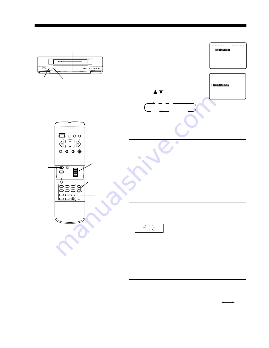
Selecting the Input Mode
MENU
SELECT : ROTATE WHEEL
SET : PUSH WHEEL
END : PUSH MENU KEY
SET UP VCR
SET C LOCK
SET UP CHANNEL
I D I OMA / LANGUE : ENGL I SH
SET UP VCR
SELECT : ROTATE WHEEL
SET : PUSH WHEEL
END : PUSH MENU KEY
REPEAT PL AY : ON
BEEPER : ON
I NPUT SELECT
: L I NE
SET AUD I O MODE
2
1
Push VCR/TV while recording is in progress to turn off
the VCR indicator in the Multi Function Display.
Use the TV channel controls to select a program.
The VCR will continue to record your program while
you watch any channel you choose.
• Switch back and forth between the recording and viewing
channel with the VCR/TV selector.
1
2
Selecting Channels at the VCR
Turn TV on.
Use VCR CH Up/ Down buttons to select channels
for viewing or recording.
• To resume TV control channel selection, push VCR/TV
to turn VCR indicator off, or simply turn VCR off.
VCR
If indicator doesn’t light, push VCR/TV to turn it on.
Multi- Function
Display
Watching Another TV Program
Rapid Tune
Push R-TUNE to display the last
channel you were watching.
• When selecting channels with the VCR CH
Up/Down buttons, channels must be
displayed for at least 4 seconds in order for
the VCR to recognize them as a new
selection.
CH08
CH10
Previous Present
Channel Channel
VCR CH
Up/Down
VCR/TV
VCR CH
UP/DOWN
WHEEL
Multi Function Display
2
1
Push MENU to display the menu.
Rotate and push the Wheel to select
“SET UP VCR.”
Rotate the Wheel to select “INPUT
SELECT” and then, push to choose
TUNER or LINE.
MENU
• You can also select “LINE” using the
VCR CH
/
buttons. The numbers
will change in the order shown.
3
1
2
3
125
LINE
(CATV)
69
(TV)
or
• When LINE is selected, “L” is displayed in the
Multi Function Display for about 4 seconds.
Summary of Contents for Omnivision PV-4651
Page 14: ...Fig 2 3 14 ...
Page 27: ...Fig 11 1 1 27 ...
Page 40: ...Fig D1 40 ...
Page 42: ...Fig D2 42 ...
Page 43: ...Fig D3 43 ...
Page 44: ...Fig D4 44 ...
Page 45: ...Fig D5 45 ...
Page 46: ...Fig D7 46 ...
Page 47: ...Fig D8 47 ...
Page 51: ...Fig M2 1 Fig M2 2 51 ...
Page 53: ...Fig M4 1 53 ...
Page 77: ...Fig M19 77 ...
Page 84: ...Fig J5 84 ...
Page 85: ...Fig J6 85 ...
Page 87: ...Fig J9 87 ...
Page 88: ...Fig J10 88 ...
Page 89: ...Fig J11 89 ...
Page 90: ...Fig J12 90 ...
Page 91: ...Fig J13 91 ...
Page 92: ...Fig J15 92 ...
Page 93: ...93 ...
Page 96: ...96 ...
Page 102: ...with the holes on the Pinch Lift Cam as shown in Fig A6 102 ...
Page 103: ...103 ...
Page 105: ...Fig K1 105 ...
Page 106: ...Fig K2 106 ...
Page 107: ...Fig K3 107 ...
Page 109: ...Fig B1 109 ...
Page 114: ...Fig E1 4 3 2 HOW TO READ THE ADJUSTMENT PROCEDURES 114 ...
Page 115: ...Fig E2 115 ...
Page 134: ...R6004 ERJ6GEYJ333V MGF CHIP 1 10W 33K 134 ...
Page 136: ...R6085 ERJ6GEYJ223V MGF CHIP 1 10W 22K 136 ...
Page 140: ...C4601 ECEA1CKA100 ELECTROLYTIC 16V 10 140 ...
Page 147: ...R6065 ERJ6GEYJ223V MGF CHIP 1 10W 22K 147 ...
Page 167: ...9 11 Operation Block Diagrams 1 167 ...
Page 178: ......
Page 204: ......
Page 205: ......