


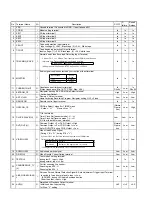
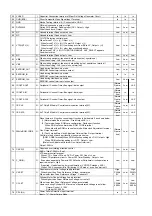


No.
Terminal Name
I/O
Description
P. OFF
P.
failure
Reset/
Releas
1
VSS
Unused terminal. Connected to GND. ( Input taken as 0V)
2
CODE1
I
Model setting terminal.
In
In
In
3
KEY1
I
AD Input terminal 1.
In
In
In
4
KEY2
I
AD Input terminal 2.
In
In
In
5
KEY3
I
AD Input terminal 3.
In
In
In
6
KEY4
I
AD Input terminal 4.
In
In
In
7
S-PHOT
I
Tape end detection Input terminal
Input voltage:(1) >2.6V, Black tape (2) >2.4V, White tape
In
In
In
8
T-PHOT
I
Tape beginning detection Output terminal
Input voltage: (1) >2.6V, Black tape (2) <2.4V, white tape
In
In
In
9
TRACKING_ENVE
I
Normal head Video Envelope Detecting Input Terminal
In
In
In
10 MO/ST/BI
I
Audio signal condition detected by current tuner Input terminal
In
In
In
11 CURRENT.LIMIT
O
Capstan current limit control terminal
(Output inpedance: Min:1K, TYP:2.5K, Max: 4.0K)
In
DA=0V
Low
In
DA=0V
12 EEPROM_CS
O
Navigator back-up EE PROM Chip Select terminal
Active Low Output
High
Low
High
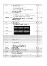
13 ART.V/H/N
O
Dummy V Output terminal
However,during Recording Program Navigator writing, Hi-Z = Fixed.
Low
Low
Low
14 REMOCON
I
Remote control input terminal
In
In
In
15 OPECON_CS
O
CS(Chip Select) signal for TIMER micon
Active = " H " Non-active = "L"
(Normal
Opera-
tion)
Low
High
16 CLOCK.SLAVE(H)
O
1) In test mode:
Timer Clock Adj [transmit mode] : H --> L
Timer Clock Adj [receive mode] : L --> H
2) Other than test mode : always L
Low
Low
Low
17 DVD_OUT(H)
O
Common Output = For DVD, Output = High
Common Output = For VCR, Output = Low
As for DVD/VTR during P.Off, Output = Low
Normal
Opera-
tion
Low
Low
18 VIDEO.H.SW
O
Video Head Switch Signal
( During L'/R = "H", during R'/L = "L" )
Low
Low
Low
19 AUDIO.H.SW
O Audio head switch signal
Low
Low
Low
20 D.REC(H)
O Video Record Current timing terminal
Low
Low
Low
21 TEST2(H)
I
Test mode 2 setting terminal
during test 2, Input = High
during normal, Input = Low
In
In
In
22
PROGRESSIVE_TV
(L)
I
Port for scanning line control:
Scanning line 628 : H
Scanning line 624 : L
Low
Low
Low
23
ABS_NORM(L)/A.AD
J
I
Serve as Forced Normal Selection Signal & Auto Adjustment Trigger Input Terminal
to switch to forced normal audio, Input = Low
(ADUBPS, during HiFi Audio Envelope decline
Other than that, Input = High
In
In
In
24 AVR(L)
O
Simplified AI Playback Output terminal
Initial condition: Input setting
1st Step : "L" setting
Hi-Z
Hi-Z
Hi-Z
Input Voltage
Sound
mode
>2.3V
Bilingual
>0.85V, <2.3V
Stereo
Cylinder FG= 1 or 4, Ref time taken as Input time until PGMM time.
Timing calculation is performed based on the following.
Normal Head
Ref time
10 u Head
Ref time + 120 degree time 1H (=64us)
*120 degree time is defined as NTSC:11122us,PAL 13333us
Cylinder FG = 1 or 4 Base From Input time until PGMM time taken as
reference time. Timing calculation is performed as follow.
Normal head
Ref time + 90 degree time
*90 degree time is defined as :NTSC : 8400us,PAL: 10000 us
Summary of Contents for NV-VP31GL
Page 7: ...7 ...
Page 8: ...8 ...
Page 30: ...7 REMOVAL OF THE POWER C B A Remove Screw D Fig D3 Remove 2 Screws P Fig D7 30 ...
Page 34: ...8 2 Traverse P C B 1 Unscrew the screws 2 Remove the solders 3 Remove the connectors 34 ...
Page 73: ...18 2 DVD MECHANISM CHASSIS PARTS SECTION 73 ...
Page 74: ...74 ...
Page 75: ...18 3 CASING PARTS SECTION 75 ...
Page 76: ...76 ...
Page 77: ...18 4 PACKING PARTS SECTION 77 ...
Page 88: ...C5004 ECJ1VB1H103K CHIP CAPACITOR 88 ...
Page 101: ...101 ...
Page 103: ...IC7551 PNA4618M12VT IR RECEIVER 103 ...
Page 137: ... VEP06F50A NV VP31GL GC GCS FRONT SW C B A 1 A B 2 3 4 5 ...
Page 138: ...NV VP31GL GC GCS FRONT JACK C B A VEP04849A 1 A B C 2 3 4 5 ...
Page 142: ... REP3406A 1N 1 A B C D E F 2 3 4 FOIL SIDE COMPONENT SIDE NV VP31GL GC GCS TRAVERSE C B A ...
Page 143: ......
Page 144: ......


