1. INTRODUCTION
1.1. INTRODUCTION
This service manual contains technical information which will allow service personnel to
understand and service this model.
If the circuit is changed or modified, this information will be followed by supplementary service
manual to be filed with original service manual.
Note:
1. Adjustment procedures, Disassembly Procedures and Assembly
Procedures for Mechanism Chassis are separate volume from this
service manual. / Please refer to the service manual for Z-
Mechanism Chassis. (Order No. VRD9802005C2)
2. The Model No. is indicated on the Schematic Diagram and Circuit
Board Diagrams as follows.
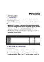
Model No.
Indication Mark
NV-HV65EC
(A)
NV-HV60EB
(B)
NV-HV60EBL
(C)
NV-HV60EC
(A)
NV-HV60EP
(D)
NV-HV55EC
(A)
NV-HV50EC
(E)
1.2. ABOUT LEAD FREE SOLDER (PbF)
Distinction of PbF PCB:
PCBs (manufactured) using lead free solder will have a PbF stamp on the PCB.
Caution:
- Pb free solder has a higher melting point than standard solder,
Typically the melting point is 50-70°F (30-40°C) higher. Please use
2


