1 INTRODUCTION
1.1. INTRODUCTION
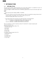
This service manual contains technical information which will allow service personnel´s to understand and service this
model.Please place orders using the parts list and not the drawing reference numbers.
If the circuit is changed or modified, this information will be followed by supplement service manual to be filed with original service
manual.
Note 1:
These movie camera uses AC Adaptor VSK0651A or VSK0651B.
Note 2:
1) This service manual does not contain the following information, because of the impossibility of sevicing at component level.
1. Schematic Diagram, Block Diagram and P.C.B. layout of Main P.C.B./ Sub P.C.B.
2. Parts List for individual parts of Main P.C.B./ Sub P.C.B.
2) The following category is/are recycle module part. Please send it/them to Central Repair Center.
*Main P.C.B. (VEP03G73AA: NV-GS230EG/E/EB/EP/EF, VEP03G73AB: NV-GS230EK,
VEP03G73AC: NV-GS230GC/GN, VEP03G73AD: NV-GS238GK)
*Sub P.C.B. (VEP23670A: NV-GS230EG/E/EB/EP/EF/EK/GC/GN, GS238GK)
When a part replacement is required for repairing each Main P.C.B. and Sub P.C.B., replace the assembly parts.
(Main P.C.B. and Sub P.C.B.)
The following circuits are contained in Main P.C.B.
1. Main Connection Circuit
2. AVIO Circuit
3. Video Circuit
4. Power Circuit
5. Control Circuit
The following circuits are contained in Sub P.C.B.
1. Sub Connection Circuit
2. LCD Circuit
3. Lens Drive Circuit
4. Sub Power Circuit
5. Camera Circuit
4
NV-GS230EG
Summary of Contents for NV-GS230E
Page 2: ...2 NV GS230EG ...
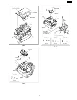
Page 10: ...Fig D3 Fig D4 Fig D5 Fig D6 10 NV GS230EG ...
Page 11: ...Fig D7 Fig D8 Fig D9 11 NV GS230EG ...
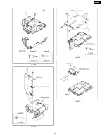
Page 12: ...Fig D10 Fig D11 Fig D12 Fig D13 12 NV GS230EG ...
Page 13: ...Fig D14 Fig D15 Fig D16 Fig D17 13 NV GS230EG ...
Page 14: ...Fig D18 Fig D19 Fig D20 Fig D21 14 NV GS230EG ...
Page 15: ...Fig D22 Fig D23 15 NV GS230EG ...
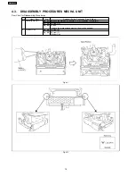
Page 17: ...Fig M3 17 NV GS230EG ...
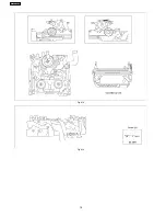
Page 18: ...Fig M4 Fig M5 18 NV GS230EG ...
Page 19: ...Fig M6 19 NV GS230EG ...
Page 22: ...How to use extension cables Fig T1 22 NV GS230EG ...
Page 26: ...Fig E3 Rough image of set up connection 26 NV GS230EG ...
Page 31: ...Fig D2 Fig D3 31 NV GS230EG ...
Page 44: ...NV GS230EG 44 ...
Page 50: ...NV GS230EG 50 ...
Page 51: ...12 EXPLODED VIEWS 12 1 FRAME CASING SECTION 1 51 NV GS230EG ...
Page 52: ...12 2 FRAME CASING SECTION 2 52 NV GS230EG ...
Page 53: ...12 3 LCD SECTION 53 NV GS230EG ...
Page 54: ...12 4 CAMERA LENS SECTION 54 NV GS230EG ...
Page 55: ...12 5 VCR MECHANISM SECTION 55 NV GS230EG ...
Page 56: ...12 6 PACKING PARTS ACCESSORIES SECTION 56 NV GS230EG ...


