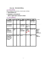
(PAL: VFJ8125H3F) and adjust it if necessary.
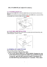
2.3.2. CHECKING OF MAIN C.B.A.
When servicing the MAIN C.B.A., take out the MAIN C.B.A. and mechanism from the frame and
turn over.
And then connect the Extension Cable (VFK2744) between the POWER C.B.A. connector (P1103)
and the MAIN C.B.A. connector (P1001) as shown in
Fig. S8
.
Fig. S8
2.3.3. FLAT CARD CABLE INSTALLATION
When installing the Flat Card Cable on the connector, install the Flat Card Cable with the cable
contacts facing the connector contacts.
Fig. S9
2.4. REMOVAL OF CASSETTE TAPE
There are 2 ways to remove a cassette tape.
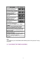
1. Service Information Display Operation
A. Turn on the Service Mode by: / (NV-FJ762EE) / Rotating the Jog
dial to fully FF side and press the EJECT key simultaneously for
3 seconds. / (NV-FJ617EE and NV-FJ712EE) / Pressing the FF
and the EJECT key simultaneously for 3 seconds. / Then select
9
Summary of Contents for NV-FJ617EE
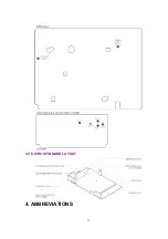
Page 23: ...3 3 8 CIRCUIT BOARD LAYOUT 4 ABBREVIATIONS 23 ...
Page 26: ...10 2 CASING PARTS SECTION 26 ...
Page 27: ...10 3 PACKING PARTS SECTION 27 ...
Page 28: ...11 REPLACEMENT PARTS LIST 28 ...
Page 120: ... VEP07992C 1 A C B 3 2 4 P6501 C 3 ADDRESS INFORMATION AV FRONT C B A Connector ...
Page 122: ... VEP06C48A NV FJ762EE 1 A C B 3 2 P6401 A 1 ADDRESS INFORMATION REAR EDIT C B A Connector ...


