


14
If “– – ” Appears under “Pos/Name” after
Entering a ShowView Number
Pos/Name stands for Programme Position/TV Station Name.
Normally, the name of the TV station or the number of the
programme position is displayed under “Pos/Name”.
However, if the TV station information was not automatically
set during Auto Setup due to adverse reception conditions,
the “– – ” indication appears instead.
In such a case, follow the operation steps below to correct it.
Press the Channel buttons
:
repeatedly to select the programme
position on which the TV programme
to be recorded will be broadcast.
After you have entered the information of a TV station, it
remains stored in the VCR’s memory, and you do not need to
enter it again in the future.
To Programme with the
ShowView Function
The ShowView numbers assigned to each TV programme
and published alongside the TV programme listings in
newspapers and magazines make it extremely easy to set
the VCR for timer recording.
The duration of a timer recording programmed with
ShowView number may be slightly longer than the actual
duration of the TV programme.
Preparations
≥
Confirm that the VCR is on.
≥
Confirm that the TV is on and the VCR viewing channel is
selected.
≥
Insert a video cassette with an intact erasure prevention
tab.
≥
Set the VCR/TV switch
N
to “VCR”.
Example:
Programming a timer recording of a TV programme with the
ShowView number 920126
Operations
1
Press the SHOW VIEW button
K
to display the menu
for entering the ShowView number on the TV.
2
Press the Numeric buttons
2
to enter the ShowView
number.
≥
If you have entered a wrong
digit, press the Cursor button
(
2
)
P
and then enter the
correct digit.
3
Press the OK button
R
to display the programmed
content.
4
Press the SP/LP button
D
to set the desired tape
speed.
≥
SP provides standard
recording time and
optimum picture quality.
LP provides doubled
recording time with slightly
reduced picture quality.
Regarding the “A” indication, refer to page 15.
≥
To extend the ending time or to make any corrections,
use the Cursor button (
3421
)
P
, the Channel
buttons
:
, the DATE button
;
, the ON button
F
, the
OFF button
E
, the SP/LP button
D
.
≥
See page 15 for VPS/PDC recording.
5
Press the TAPE button
B
to select the corresponding
cassette tape length.
(See page 26.)
6
Press the OK button
R
again to conclude the
settings.
≥
To programme additional
timer recordings, repeat
operation steps 1–6.
ShowView
9 2 0 1 2 6
VCR
On Screen Display
ZDF
27/10
20:00
21:30
SP
ON
/
:
:
/
:
:
/
:
:
/
:
:
Pos
Start Stop
SP
VPS
Name
DATE
ON
OFF
LP
PDC
Timer recording
VCR
ZDF
27/10
20:00
21:30
SP
ON
/
:
:
/
:
:
/
:
:
Pos
Start Stop
SP
VPS
Name
DATE
ON
OFF
LP
PDC
Timer recording
VCR
To Suspend the Timer Recording Standby
Mode
When you want to use the VCR for playback, normal
recording or some other operation before the programmed
timer recording will be performed, you can temporarily
suspend the timer recording standby mode by
pressing the TIMER REC button
C
so that the “
Á
” indication
on the VCR display disappears.
However, after you have finished using the VCR, be sure
to reactivate the timer recording standby mode by pressing
the TIMER REC button
C
again, otherwise the programmed
timer recording will not be performed.
Note:
≥
If the VCR is not put in the timer recording standby mode at
the latest 10 minutes before the programmed timer
recording starting time, the “
Á
” indication flashes on the
VCR display. In this case, press the TIMER REC button
C
to put the VCR in the timer recording standby mode.
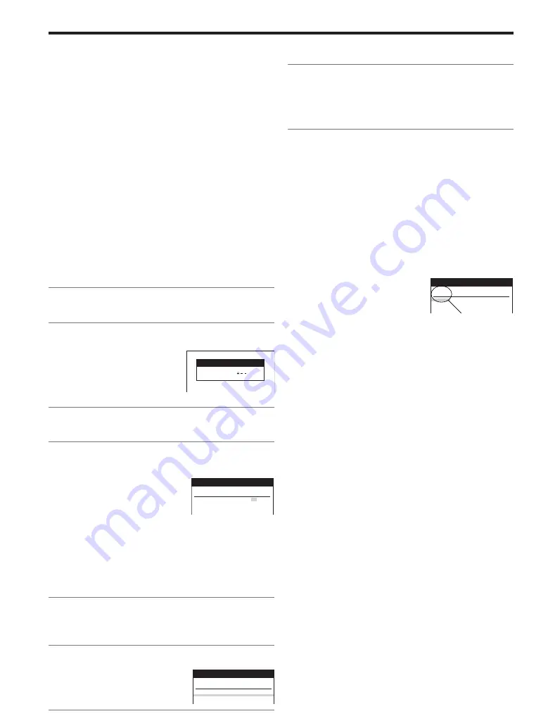
Timer recording
VCR
15:00
17:00
SP
/
:
:
/
:
:
/
:
:
/
:
:
Pos
Start Stop
SP
VPS
Name
DATE
ON
OFF
LP
PDC
“– – ” indication
7
Press the TIMER REC button
C
to switch the VCR
over to the timer recording standby mode.
≥
Check that “
Á
” is lit on the VCR display.
If it is flashing, check the timer recording details again.
(See page 15.)
Summary of Contents for NV-FJ603EL-K
Page 13: ...3 1 2 DETAIL OF DISASSEMBLY METHOD 1 REMOVAL OF THE TOP PANEL Remove 4 Screws A Fig D2 13 ...
Page 23: ...3 3 8 CIRCUIT BOARD LAYOUT 4 ABBREVIATIONS 23 ...
Page 24: ...24 ...
Page 25: ...25 ...
Page 26: ...26 ...
Page 27: ...5 INPUT OUTPUT CHART 5 1 INPUT OUTPUT CHART FOR IC6001 Fig MP1 27 ...
Page 28: ...Fig MP2 28 ...
Page 29: ...Fig MP3 29 ...
Page 30: ...Fig MP4 30 ...
Page 31: ...5 2 TRUTH TABLE 5 2 1 EXCEPT B S B K BL K MODEL 31 ...
Page 35: ...NOTE THIS TABLE IS ONLY FOR B S B K BL K MODEL 35 ...
Page 38: ...8 6 NICAM DECODER PACK C B A 9 EXPLODED VIEWS 9 1 CHASSIS PARTS SECTION 38 ...
Page 39: ...9 2 CASING PARTS SECTION 39 ...
Page 40: ...9 3 PACKING PARTS SECTION 40 ...
Page 41: ...10 REPLACEMENT PARTS LIST 41 ...
Page 53: ...53 ...
Page 60: ...L3009 VLQ0599J390 COIL 39UH 60 ...
Page 74: ...L6001 VLQ0599J101 COIL 100UH 74 ...
Page 88: ...L7707 VLQ0599J220 COIL 22UH 88 ...
Page 102: ...LB3501 04 VLP0145 COIL 102 ...
Page 128: ...K0707 ERJ3GEY0R00 M RESISTOR CH 1 16W 0 128 ...
Page 138: ...Ref No Part No Part Name Description VJS3537B009G CONNECTOR FEMALE 9P 138 ...
Page 147: ......
Page 148: ... C F A B D E G H J ...
Page 151: ......