background image

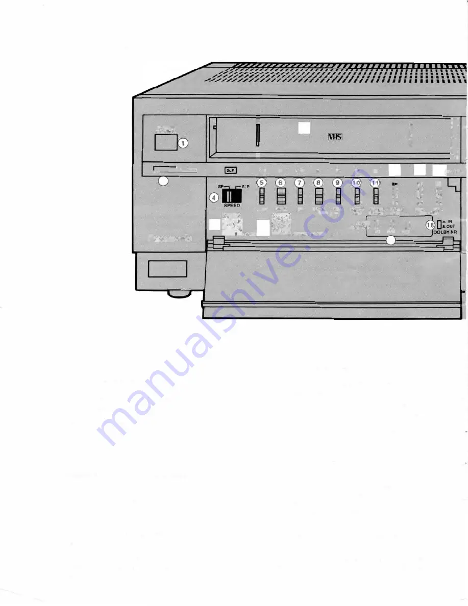
CONTROLS AND COMPONENTS 

FRONT 

REMOTE 

CONTROL 

__ __.,A.EJECT 

-

® 

-

... • 

REW 

STOP 

FF 

PLAY 

REC 

=

II 

AUDIO  PAUSE 

FRAME 

D

U

B  /STILL  ADV 

� 

� 

@u

sH-OPEN 

El 

El 

8  8 

REV 

FWD 

SEARCH 

Panasonic 

�  �  L-

.

� 

@

�RACKI� \.Q}Sl.OWTRACKING 

A

UDI

a

MONITOR 

CH1 

a  a 

CH2  MIX 

G)

Remote  Control  Sensor-

receives 

signal  from

Wireless Remote Control.

@

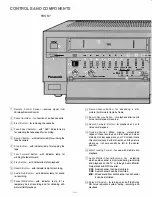
Cassette Holder-

for 

insertion of a video cassette. 

@

Eject Button-

for 

removing the cassette. 

0

Tape Speed Selector-

with 

"SLP" indicator lamp 

for selecting the tape speed for recording. 

® 

Rewind Button-

with 

indicator lamp for winding the

tape backward. 

@

Stop  Button-

with 

indicator lamp for  stopping the 

tape. 

(j) 

Fast  Forward  Button-

with 

indicator  lamp  for

winding the tape forward. 

@

Play Button-

with 

indicator lamp for playback. 

@

Record Button-

with 

indicator lamp for recording. 

@

Audio  Dub  Button-

with 

indicator lamp for  sound 

re-recording. 

<D) 

Pause/Still Button-

with 

indicator  lamp  for  a

temporary  halt  of  recording  and  for  obtaining  still­

picture (field) playback. 

-5-

17 

@

Frame Advance Button-

for 

advancing  a  still­

picture (field) picture frame by frame. 

@

Search Reverse Button-

for 

playback at twice or 8 

times normal speed in reverse. 

@

Search  Forward  Button-

for 

playback  at  4  or  8 

times normal speed. 

@

Tracking Control-

When 

playing  prerecorded 

tapes  or  those  recorded  on  other  units  and  when 

distortion (noise) appears on your TV screen, rotate 

this control slowly in either direction until the picture 

clears  up.  It  should  usually  be  left  in  the  center 

position. 

@

Slow Tracking Control-

for 

use with multi-motion 

playback. 

@

Audio  Monitor Channel Buttons-

for 

selecting 

which audio channel is monitored during recording 

and playback  on the  TV  or  through Audio  Monitor 

Output Jack and RF Converter. 

CH1: 

Audio channel 1  can be monitored. 

CH2: 

Audio channel 2 can be monitored. 

MIX:  Mixed sound from both channel 1 and channel 

2 can be monitored. 

@

Dolby NR Switch-

for 

turning on and off the Dolby 

NR  noise  reduction  system  during  recording  and 

playback. 

Summary of Contents for NV-8950

Page 1: ... VI IS NV m rn Video Cassette Recorder Before attempting to connect operate or adjust this product please read these instru tions completely VQT0884 2 ...

Page 2: ... one video cassette tape The INDEX SELECT Buttons searches the desired recording start point and start playback immediately IBLANK DETECT Button This button searches any blank unrecorded part of the tape extending for 14 seconds in the fast forward mode about 3 minutes in the SP mode or about 9 minutes in the SLP mode during recording or playback The tape is then brought to the start of theblank p...

Page 3: ...l MOTION PLAYBACK 16 CAMERA RECORDING 17 AUDIO DUBBING 18 RE RECORDING 19 SPECIAL FUNCTIONS OF YOUR VCR 23 WIRELESS REMOTE CONTROL 25 DEW CONDENSATION 26 BEFORE REQUESTING SERVICE Back Cover SPECIFICATIONS WARNING TO PREVENT FIRE OR SHOCK HAZARD DO NOT EXPOSE THIS EQUIPMENT TO RAIN OR MOISTURE CAUTION TO REDUCE THE RISK OF ELECTRIC SHOCK DO NOT REMOVE COVER OR BACK NO USER SERVICEABLE PARTS INSIDE...

Page 4: ...tion and do not place anything heavy on it Take special care not to use or store the unit for a long period of time in direct sunlight in excessively hot cold damp or dusty places or places subject to heavy vibrations Do not insert fingers or any other objects into the cassette holder 1 pc 300 ohm 75 ohm 1 pc Coaxial cable transformer _ w th one touch typ e VFA0010 F connector VJA0147 2 pcs Batter...

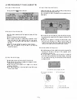
Page 5: ...top Button Lamp lights up with the power on Before trying to insert the cassette into the cassette holder check that the Stop Button Lamp is off to make sure the cassette holder is empty Never try to disassemble the cassette or splice the tape Don t open the cassette touch the tape or put anything inside the cassette Accidental Erasure Prevension Video Cassette Storage Avoid places where humidity ...

Page 6: ... lamp for a temporary halt of recording and for obtaining still picture field playback 5 17 Frame Advance Button for advancing a still picture field picture frame by frame Search Reverse Button for playback at twice or 8 times normal speed in reverse Search Forward Button for playback at 4 or 8 times normal speed Tracking Control When playing prerecorded tapes or those recorded on other units and ...

Page 7: ...r lamp for checking remaining time on the tape Power Switch with indicator lamp for turning the unit on and off VTR TV Selector with VTR indicator lamp for selecting which signal is to be viewed on the TV VTR for playback of the video recording or monitoring of recording TV for normal TV viewing or viewing one broadcast while recording another Input Signal Selector for selecting the input signal t...

Page 8: ... for connecting the cable supplied to the UHF IN jack of the TV set UHF Antenna Input Connectors for connecting the unit to the UHF antenna VHF Antenna Output Connector for connecting the cable supplied to the VHF IN jack of the TV set VHF Antenna Input Connector for connecting the unit to the VHF antenna 7 CH3 CH4 D OUT OUT IN ...

Page 9: ...ting a video cable to a TV monitor etc Audio Monitor Output Jack for connecting an audio cable of a TV monitor to allow monitoring of channel 1 channel 2 or mixed audio by pushing the Audio Monitor Channel Buttons Vertical Lock Adjusters on the bottom for cor recting the vertical jitter which may be caused during multi motion playback as a result of the connections between the VCR and the TV set M...

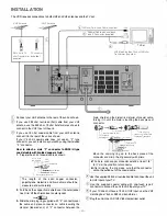
Page 10: ...g ring supplied with F connector over Coaxial Cable with one touch type F Connector supplied TV Set VHF Matching Box 75 ohm 300ohm Transformer supplied l J I 1111111111111111111 1 1111111111111111111 1111111111111111111 O 1111111111111111111 V 1111111111111111111 0 braid shield and the dielectric material of coaxial cable forcing it in until the braid is touching the back piece of connector LLL L ...

Page 11: ... when in the PLAY mode Remember your TV must be tuned to the channel you select on the unit l J nwl CHICH4 IN UHF HF ll 1111111111111111111 1111111111111111111 AC IN 1111111111111111111 u v 1111111111111111111 Y 1111111111111111111 CONNECTION OF THE UNIT WITH A TV MONITOR TV monitor and pre amplified stereo phonograph 1 J g I IQJ IQJ I I I J nm I I I L_____ ______J To Video Input To Audio Inputs 1...

Page 12: ...selected This lamp will also light up when the tape recorded in SLP mode is played Push this button to open thefrontcover 00 ao Reset 0000 ON VTR Push in the video cassette with the window side facing up and the printed arrow pointing away from you and press with your finger until it is pulled inside The cassette can be loaded only when the VCR is powered Do not force the cassette into the cassett...

Page 13: ...e tape from being damaged Turn VCR and TV OFF To watch TV normally o CJ G Turn VCR OFF The VTR TV Selector changes to TV automatically 12 I al e e I I I I I I I I I e n nn L U UU When the tape reaches its end the tape will be rewound automatically j ajjCMWaj e e I I I I I I I I I NO CJ Turn the TV ON 3 Select the CHANNEL _ iii _ n L U UU to be viewed ON Select desired channel on the TV ...

Page 14: ...omatically Note This model is not designed to accommodate LP tapes Please dub them first using another VCR which is capable of LP playback I cl s e D I I I I I D I I _ ax m u u LJ __ lg o o o oli j LIIIOel NI ECT__J MEMORY SWITCH N JEX NO CURRENT SELECTS H LIU I_J I J LREfllA TIMEJ Memory Indicator J IDCI BYSYSTEM I RESET CJ MEMORY ON Memory Switch TheMemory Switch is useful when you wish to start...

Page 15: ..._ When SEARCH FORWARD Button is h ld down d ring playback of tape recorded in the SLP mode pictures at 8 times normal speed will be played When the tape recorded in the SP mode is played back pictures at 4 times normal speed will be played 0 II I SEARCH REVERSE playback i SEARCH FORWARD When SEARCH REVERSE Button is held down during playback of the tape recorded in the SLP mode pictures at 8 times...

Page 16: ...10 and x1 3 slow reverse playback mode is established When the control is rotated in the 83 area the search reverse mode is established When the control is released it returns to the x1 3 mark Push the SEARCH Button or Play Button to stop variable speed or slow reverse playback When playing back a tape in multi motion on a TV set equipped with an automatic vertical hold function the picture may sh...

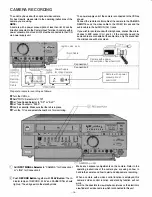
Page 17: ...I Prepare for camera recording as follows eTurn the VCR on Set VTR TV Selector to VTR e SetTape Speed Selector to SP or SLP e SetTape Counter to 0000 Pow v l IJ e Insert a cassette Make sure that the tab is in place eTurn theTV on and select channel 3 or 4 for monitoring o CJ I Im I I I I I I G Set INPUT SIGNAL Selector to CAMERA for Connection 1 or LINE for Connection 2 Push RECORD Button togethe...

Page 18: ...place where you want the dub to begin Push AUDIO DUB Button together with PLAY Button Push PAUSE STILL Button once again to release the tape frompause Audiodubbing will start Push STOP Button to stop audio dubbing 17 jc cj s e D D I I D I D a a llll WLM LI IJ I_ILI _ _ U IICH 11 DUICT aVJtf SU 10 1 ITART t CJ r 1Q lllll s c s When a microphone is used for dubbing do not get it near the speaker of ...

Page 19: ...o AUDIO IN CH1 on the recording machine using an audio cable Audio cable can be ordinary audio shielded type e Set Input Signal Selector on the recording machine to LINE e Turn both units on e Set VTR TV Selector on the recording machine to VTR e For monitoring of re recording turn the TV on and select channel 3 or 4 PLAY REC o Ci 2l G Place the recorded cassette in the playback machine and a blan...

Page 20: ...tly Therefore when Dolby NR is used during recording this should be noted on the cassette label for easy identification when sub sequently playing back INDEX SELECT Button I Audio Monitor Channel Button CH1 MIX CH2 Audio Monitor Output Jacks RF Converter Audio from channel1 only Sound from both channels will be mixed Audio from channel2 only Every time recordings take place this VCR records the po...

Page 21: ... rewound and the CURRENT number 1 is indicated MEMORY CJ a 0 D L INDEX The tape starts to move automatically and when the SELECTED number and the CURRENT number coincide playback starts CUINNT NO MNT 12 12 CJ L J CJ fl CT 8ET RQl T 10 AIIIAINING START TIME Cl a D a a 01 e e 8 8 I I I I I I I tll AMOUECT 191 INDEX SELECT Buttons Once playback has started INDEX numbers disappear and the displayretur...

Page 22: ...d as follows 1 Push the RECORD Button on the VCR 2 Push the camera s starVstop switch recording does not start yet 3 Push the RECORD Button together with the PLAY Button to start recording I BLANK DETECT Button I This button is used to search any blank unrecorded part of the tape extending for 14 seconds inthe fast forward mode about 3 minutes in the SP mode or about 9 minutes in the SLP mode duri...

Page 23: ...J MEMORY LREMA_r_J CJ REMAINING fECT SET RESET 10 1 START TIME Cl D D D D g L INDEX SELECT __J When C appears it means that the remaining time is being counted Wait for between 20 and 50 seconds and thenpressthe button again INDEXNO RESET CUMENT l Cm CJ MEMORY L__ _J CJ REMAINING ECT SET RESET 10 1 START TIME Cl D D D D g L INDEX SE T __J NOTE This function does not work with tapes not made on thi...

Page 24: ...ieswiththeir polarities and 8 aligned properly Do not heat disassemble or shortcircuit the old batteries If you do not intendto use the remote control for a long period of time remove the batteries and store them in a cool dry place Remove spentbatteries immediately and dispose ofthem Do not mix old and new batteries Also never mix alkaline batteries with manganese batteries 23 Channel Selection B...

Page 25: ...is aimed away from the VCR This happens because the infra red beam will bounce off the walls of the room and eventuallyreach the remote sensor Note that furniture can block the path and dark walls may totally absorb the light If the room receives a lot of sunshine you may find that the commands are masked by the bright light Block off the sunlight Remote Control Sensor Bouncing may work but aim di...

Page 26: ...ghts up to protect the tape and the video heads and all the function buttons except the EJECT Button are disabled The formation of dew is a gradual process and so the Dew Indicator Lamp may not light for between 1 O and 15 minutes after the dew starts to form When the unit is in a room where the temperature or humidity changes suddenly wait about 20 minutes and then check the Dew Indicator Lamp Wh...

Page 27: ...dio Check that the video recorder and Dubbing equipment required for the camera recording or audio dubbing operations is connected properly Check that the Input Signal Selector has been set to the correct position If the top of your playback picture waves Locate the horizontal hold control on back and forth excessively yourTV set Turn it slowly to correct for the wavy picture If there is no such c...

Page 28: ... 41 F 104 F 5 C 40 C 35 80 36 3 lbs 16 5 kg 17 3 4 W x6 5 8 H x16 13 16 D 450 W x168 H x426 D mm Weight and dimensions shown are approximate Specifications are subject to change without notice PANASONIC INDUSTRIAL COMPANY Division of Matsushita Electric Corporation of America Executive Office One Panasonic Way Secaucus New Jersey 07094 201 348 7000 75D unbalanced 75D unbalanced 75D unbalanced 5 kD...

Reviews: