27
9 Service Mode
9.1.
Self Diagnosis Display Mode
Self Diagnosis Function is available on the model and Self Diagnosis Mode is displayed on the display and control panel
at the front center of PC Door, when trouble and/or failure happens.
A : How to start
When “Super Freeze button” on the control panel is pressed more than 5 seconds, Self Diagnosis display mode
appeared.
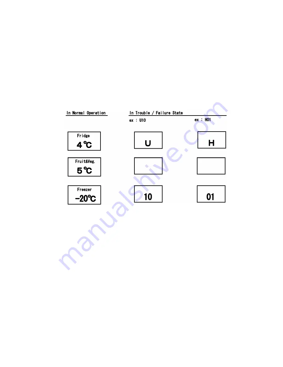
The sign is displayed at center of Fridge temperature display area and Freezer area.
And when there are more than two signs, those are appeared continuously every 1second.
Then finally “-”is displayed at Fridge area and “--” is displayed at Freezer area.
When there is not any trouble/failure, “-” is displayed at Fridge temperature area and “--” is displayed at Freezer area.
B : How to end
Self Diagnosis mode ends When “Super Freeze button” is pressed for less than 1 second while Self Diagnosis display
mode.
9.2.
Trouble / Failure history display mode
A : How to start
Trouble / Failure sign is displayed when “Super Freeze button” is pressed for more than 1 second while Self Diagnosis
display mode.
When the sign is displayed, “ - ” is displayed at left side of Freezer temperature display area.
For example: When there is a trouble of FC temperature sensor.
Fridge temperature display area: H, Freezer area: - 01
When there is not trouble/failure history.
Fridge temperature display area: H, Freezer area: ---
B : How to end
Trouble / failure history display mode ends when "Super Freeze button" is pressed for more than 1 second while that
mode.
Or 7 minutes after starting the Self Diagnosis Display mode, Self Diagnosis Mode is ended automatically.
Summary of Contents for NR-B30FG1
Page 5: ...5 2 Specifications ...
Page 6: ...6 3 General Introduction 3 1 Flow of Refrigerant ...
Page 7: ...7 4 Features and Functions 4 1 Features 4 1 1 Super Energy Saving ...
Page 8: ...8 ...
Page 9: ...9 4 1 2 Super Keep Fresh Vitamin Safe ...
Page 10: ...10 ...
Page 11: ...11 ...
Page 12: ...12 4 1 3 Super Hygienic ...
Page 13: ...13 4 2 Functions 1 2 3 4 ...
Page 14: ...14 5 6 7 8 ...
Page 21: ...21 6 Location of Controls and Components 6 1 Display and Control Panel ...
Page 22: ...22 6 2 Components ...
Page 23: ...23 7 Installation Instructions 7 1 Installation Instructions ...
Page 24: ...24 7 2 Getting started ...
Page 25: ...25 ...
Page 29: ...29 10 Troubleshooting Guide 10 1 FC and PC not cooling at all Compressor does not run ...
Page 30: ...30 10 2 PC is not cooling or poor cooling FC cooling condition is normal ...
Page 31: ...31 10 3 FC is poor cooling Compressor run ...
Page 32: ...32 10 4 VC is poor cooling or excessive cooling ...
Page 50: ...50 12 Maintenance 12 1 Automatic Defrosting 12 2 Removing and attaching shelves ...
Page 51: ...51 12 3 Care and cleaning instructions ...
Page 52: ...52 ...
Page 53: ...53 13 Dimensions 13 1 Outside NR B30FX1 NR B30FG1 ...
Page 54: ...54 13 2 Inside NR B30FX1 ...
Page 55: ...55 13 3 Inside NR B30FG1 ...
Page 56: ...56 14 Schematic Diagram 14 1 Schematic Diagram NR B30FG1 NR B30FX1 ...
Page 57: ...57 14 2 Wiring Diagram NR B30FG1 NR B30FX1 ...
Page 58: ...58 15 Exploded View and Replacement Parts List 15 1 Exploded View 1 NR B30FG1 NR B30FX1 ...
Page 59: ...59 15 2 Replacement Parts List 1 NR B30FG1 NR B30FX1 ...
Page 60: ...60 15 3 Replacement Parts List 1 NR B30FG1 NR B30FX1 ...
Page 61: ...61 15 4 Exploded View 2 NR B30FG1 NR B30FX1 ...
Page 62: ...62 15 5 Replacement Parts List 2 NR B30FG1 NR B30FX1 ...
Page 63: ...63 15 6 Replacement Parts List 2 NR B30FG1 NR B30FX1 ...
Page 64: ...64 15 7 Exploded View 3 NR B30FG1 NR B30FX1 Bundled parts The parts for left opening doors ...
Page 66: ...66 15 9 Packing Exploded View NR B30FG1 NR B30FX1 ...
Page 67: ...67 15 10 Packing Material Pats List NR B30FG1 NR B30FX1 ...


