20
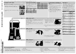
5. After releasing sockets, remove PCB box from its housing
around the box.
6. Disassemble the PCD box and its cover.
7. Remove the PCB card by depressing the taps that fix it.
8. Remove the connector that fix the LCD screen.
9. Remove the card from its housing and unplug its connec-
tor.
10. Remove the LCD screen by depressing the taps by using
a screwdriver.
Summary of Contents for NA-128VB6WSR
Page 2: ...2 1 Safety Precautions ...
Page 4: ...4 2 3 Dimension Dimension in millimetres NA 128VB6 NA 148VB6 ...
Page 5: ...5 3 Location of Controls and Components ...
Page 9: ...9 5 2 Program Details ...
Page 11: ...11 ...
Page 32: ...32 4 Remove 19 screws around tub using box wrench size 8 mm 5 Remove front tub 6 Remove drum ...
Page 42: ...42 12 Wiring Connection Diagram 12 1 Wiring Diagram Board ...
Page 43: ...43 12 2 Wiring Diagram Socket ...
Page 46: ...46 13 3 Washing Group Spare Parts 13 3 1 Exploded View of Washing Group Spare Parts ...
Page 50: ...50 13 6 Body Group Spare Parts 13 6 1 Exploded View of Body Group Spare Parts ...
Page 55: ...55 13 10 Packaging Group Spare Parts 13 10 1 Exploded View of Packaging Group Spare Parts ...


