background image


9


      FREEZER COMPONENTS 


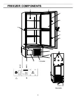
1. Control panel (on the upper front of the outer door):

    Used for temperature setting and indication 

of operating status is displayed on the panel.    See page 10 for details.


2.


Outer door:   

To open the door, grip the handle.    On closing, lock the outer door latch completely. 


3.  Inner  door:

    The  operation  of  the  inner  door  should  be  quick  to  minimize  the  temperature  rise  in 

chamber.    Lock  the  inner  door  latch  completely  when  the  inner  door  is  closed.    The  inner  door  is 
removable for cleaning or defrosting.    See page 23 “Routine maintenance”. 
 

4. Outer door latch:   

Always lock the latch when the outer door is closed.


5. Inner door latch:   

Always lock the inner door latch when the inner door is closed. 


6. Magnetic door gasket:

    This provides a tight door seal and prevents cold air leak.    Keep clean. 


7.  Access  port  (rear  and  bottom):

    This  is  used  for  leading  a  cable  and  sensor  of  a  measuring 

equipment, or nozzle of back up cooling kit to chamber. 

 
8. Air intake vent (grille):

    Do not block this vent to keep the proper cooling performance. 


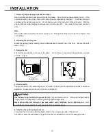
9. Caster:

    Four casters are provided to facilitate moving of the cabinet.    For the installation, adjust the 

leveling foot so that the front two casters cannot contact with the floor. 
 

10. Leveling foot:

    The height of the freezer can be adjusted by this screw type foot.    Keep the unit in 

level at the installation. 
 

11.  Condenser  filter  (behind  the  grille):

    This  filter  prevents  the  dust  from  accumulating  on  the 

condenser.    The dusty condenser filter  may  cause  failure  of  refrigerating  device.    Clean  the  condenser 
filter once a month.    See page 22 “Routine maintenance” for the cleaning. 
 

12. Space for temperature recorder:   

An automatic temperature recorder (optional component) can be 

attached here.    See page 32“ Temperature recorder (Option)”. 
 

13. Key lock:

    Turn clockwise to 180

o

 with a key and the outer door is securely locked. 


14. Air intake port:

 After closing the outer door, if used to open soon.    See page 11 

Be sure to close the cap of the air intake port after the use. 
*  Replace  the  cap  when  the  air  intake  port  is  not  used.    Improper  replacement  may  cause  rise  of 
chamber temperature or condensation around the air intake port. 
 

15. Fixture (on back side):

    Two fixtures are provided as spacers between the cabinet and wall and also 

serve as hooks to fix the unit.    See page 13 “Installation”. 

 
16. Power switch:

    This is for turning ON/OFF the power to the unit.    ON – “I”    OFF – “

” 


17.


Remote  alarm  terminal:

    This  is  used  to  notice  an  alarm  condition  of  the  unit  to  remote  location.   

Refer to page 11 “Remote alarm terminal”. 
 

18. Battery switch:

    This is a switch for a battery for power failure alarm.    Normally, turn on this switch. 

Be sure to turn off this switch if the freezer is not in operating for the long period (over one month). 
 

19. Fuse:   

AC 250 V, 5 A is attached. 

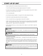
  WARNING


Fix the shelf supports and shelves securely.    Incomplete installation may cause injury or damage. 
Never touch the storage items with wet hands.    Touching with the wet hands may cause frostbite. 
Replace the cap when the air intake port is not used.    Improper replacement may cause rise of chamber 
temperature or condensation around the air intake port. 

Summary of Contents for MDF-U76V

Page 1: ...this manual for future use See page 40 for all Model Nos M M M MDF DF DF DF U76V U76V U76V U76V MDF MDF MDF MDF U76VC U76VC U76VC U76VC MDF MDF MDF MDF U56V U56V U56V U56V MDF MDF MDF MDF U56V U56V U5...

Page 2: ...G OF DOOR ALARM DELAY TIME P 20 ALARMS SAFETY FUNCTIONS P 21 ROUTINE MAINTENANCE Cleaning of cabinet P 22 Cleaning of condenser filter P 22 Defrosting of inside wall P 23 Cleaning of air intake port P...

Page 3: ...ill be subjected to change without notice due to the improvement of performance or functions Contact our sales representative or agent if any page of the manual is lost or page order is incorrect Cont...

Page 4: ...n must be followed Be sure to keep this manual in a place accessible to users of this unit Some warning and or caution labels are attached on the unit Following shows the description of such labels Th...

Page 5: ...wer supply outlet is not grounded it will be necessary to install a ground by qualified engineers Never ground the unit through a gas pipe water main telephone line or lightning rod Such grounding may...

Page 6: ...ion Disconnect the power supply plug if there is something wrong with the unit Continued abnormal operation may cause electric shock or fire When removing the plug from the power supply outlet grip th...

Page 7: ...insertion may cause a heat or ignition Never store corrosive substances such as acid or alkali in this unit if the container cannot be sealed These may cause corrosion of inner components or electric...

Page 8: ...40 o C Maximum relative humidity 80 for temperature up to 31 o C decreasing linearly to 50 relative humidity at 40 o C Mains supply voltage fluctuations up to 10 of the nominal voltage Transient overv...

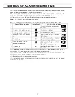
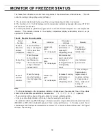
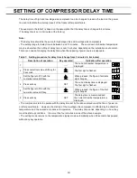
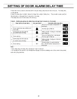
Page 9: ...8 FREEZER COMPONENTS 11 inside 7 15 1 2 3 6 8 12 7 4 9 10 13 5 Power cord 17 18 16 14 19 Rear side...

Page 10: ...condenser filter may cause failure of refrigerating device Clean the condenser filter once a month See page 22 Routine maintenance for the cleaning 12 Space for temperature recorder An automatic tempe...

Page 11: ...delay time and door alarm delay time Refer to page 15 16 17 19 and 20 for details respectively 8 Digit shift key Pressing this key in the setting mode causes the changeable digit to shift Key lock se...

Page 12: ...opened soon a door is easy to open with the following process 1 Turn the cap of the left side counterclockwise about two laps That can be removed completely 2 Put the air into the chamber from about...

Page 13: ...cause vibration or noise WARNING Install the unit on a sturdy floor If the floor is not strong enough or the installation site is not adequate this may result in injury from the unit falling or tippi...

Page 14: ...evel Fig 1 3 Fixing the unit Two fixtures are attached to the rear of the frame Fix the frame to the wall with these fixtures and rope or chain Fig 2 4 Ground earth The ground earth is for preventing...

Page 15: ...you can put articles into the chamber in a small batch to prevent the temperature rise CAUTION Do not put too many warm articles in the chamber The temperature rise may cause the damage to the articl...

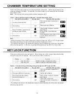
Page 16: ...load is 86 o C when the ambient temperature is 30 o C The setting mode returns to the temperature display mode automatically when 90 seconds has passed without any key operation In this case any setti...

Page 17: ...figure to 1 The first digit is flashed 4 Press set key SET The first digit is flashed 5 Scroll the figure to 005 by using digit shift key and numerical value shift key When pressed the figure of sett...

Page 18: ...is flashed 3 Set the figure to F25 with the digit shift key and numerical value shift key The settable digit is shifted When pressed the figure of settable digit changes 4 Press set key SET The curre...

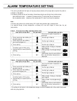
Page 19: ...ge is less than approx 195 V when the rated voltage is between 220 and 240 V status lamp lights 2 is displayed Abnormal heat at power supply outlet or degrade of starting performance of refrigerating...

Page 20: ...dication after operation 1 The current chamber temperature is displayed 2 Press numerical value shift key for 5 seconds The first digit is flashed 3 Set the figure to F05 with the numerical value shif...

Page 21: ...current chamber temperature is displayed 2 Press numerical value shift key for 5 seconds The first digit is flashed 3 Set the figure to F04 with the numerical value shift key When pressed the figure o...

Page 22: ...emote alarm If the cascade sensor is short circuited Alarm lamp is flashed E04 and chamber temp are displayed alternately Intermittent tone Remote alarm If the filter sensor is disconnected Alarm lamp...

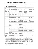
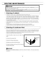
Page 23: ...the electric insulation and cause failure The compressor and other mechanical part are completely sealed This unit requires absolutely no lubrication Check the back up cooling kit by pressing test sw...

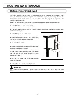
Page 24: ...r all the contents to another freezer or a container which is refrigerated by liquid carbon dioxide or dry ice 3 Turn off the power switch of the freezer 4 Open the outer door and inner door Remove th...

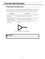
Page 25: ...ir intake port The pipe of the air intake port is thrust with a stick for air intake port cleaning of the accessories and frost is taken An outside door does not open even if the cap of the air intake...

Page 26: ...e condenser filter is clogged Always clean the condenser filter when the filter check lamp is lit The outer door is not shut tightly The inner door is not installed correctly The set temperature in th...

Page 27: ...ve doors to prevent accidents such as suffocation Recycle of battery The unit contains a rechargeable battery The battery is recyclable At the end of it s useful life check with you local solid offici...

Page 28: ...pose of them correctly at your local community waste collection recycling centre Please help us to conserve the environment we live in German F r EU Staaten Das Symbol und das erw hnte Wiederverwertun...

Page 29: ...es de mani re inappropri e peuvent s av rer potentiellement dangereuses pour la sant humaine et pour l environnement Cependant ces mati res sont n cessaires au bon fonctionnement de votre appareil ou...

Page 30: ...m recolha de lixo local Por favor ajude nos a conservar o ambiente Italian PER UTENTI UE Il simbolo e i sistemi di riciclaggio descritti di seguito si applicano esclusivamente ai paesi dell UE Questo...

Page 31: ...en bij uw plaatselijk afvalinzameling recyclingcentrum in uw buurt Help ons het milieu waarin wij leven in stand te houden Swedish F R ANV NDARE INOM EU Den symbolm rkning och de tervinningssystem som...

Page 32: ...ectric shock Disposal of nickel metal hydride battery 1 Turn off the power switch and disconnect the power supply plug 2 As shown in the Fig 2 remove six screws fixing the side cover and switch cover...

Page 33: ...Press both sides of the pen arm as indicated by the arrows to open the head clamp at A and B See to Fig 2 illustration 1 4 Position the pen cartridge so that the guide pins fit into the guide holes o...

Page 34: ...y two hours for 0 position of chart center and roughly one hour for 100 position when the recording chart speed is set to seven days When the recording chart speed is set to 32 days The center of the...

Page 35: ...5 Contact our sales representative or agent for the installation of a temperature recorder BACK UP COOLING KIT OPTION Chamber temperature is the time when 70 o C can be holding for Liquid CO2 back up...

Page 36: ...der 1 Switch of back up cooling kit BACKUP When turning on the system the back up standby lamp is brightened This means that the system is ready To stop the operation of the system turn off this switc...

Page 37: ...it up by more than 5 to the lowest set temperature when the use in a long time AN optional inventory rack IR 224U cannot be used when an small inner door is installed DRAWER RACK OPTION There is a dra...

Page 38: ...y racks securely Incomplete installation may cause injury or damage NOTE Only inventory rack IR 220U can be applied when the small inner door MDF 7ID1 or MDF 5ID1 is installed Shelf support Shelf stop...

Page 39: ...isplay Thermal sensor Platinum resistance Pt 1000 Alarm High temp alarm Low temp alarm Power failure alarm Door alarm Filter alarm Remote alarm contact Allowable contact capacity DC 30 V 2 A Battery N...

Page 40: ...hermal sensor Platinum resistance Pt 1000 Alarm High temp alarm Low temp alarm Power failure alarm Door alarm Filter alarm Remote alarm contact Allowable contact capacity DC 30 V 2 A Battery Nickel me...

Page 41: ...ground noise 20 dB Maximum pressure 2600 kPa Product name Ultra Low Temperature Freezer MDF U56V MDF U56VC Model No MDF U56V PA MDF U56VC PA Cooling performance 86 o C at the center of the chamber amb...

Page 42: ...t Unit interior No contamination Decontaminated Contaminated Others 3 Instructions for safe repair maintenance of the unit a The unit is safe to work on b There is some danger see below Procedure to b...

Page 43: ...thcare Company of North America Panasonic Healthcare Company of North America Panasonic Healthcare Company of North America Panasonic Healthcare Company of North America 1300 Michael Drive Suite A Woo...

Reviews: