background image

11

according to the respective instructions.

3.5.

BRUSH REPLACEMENT

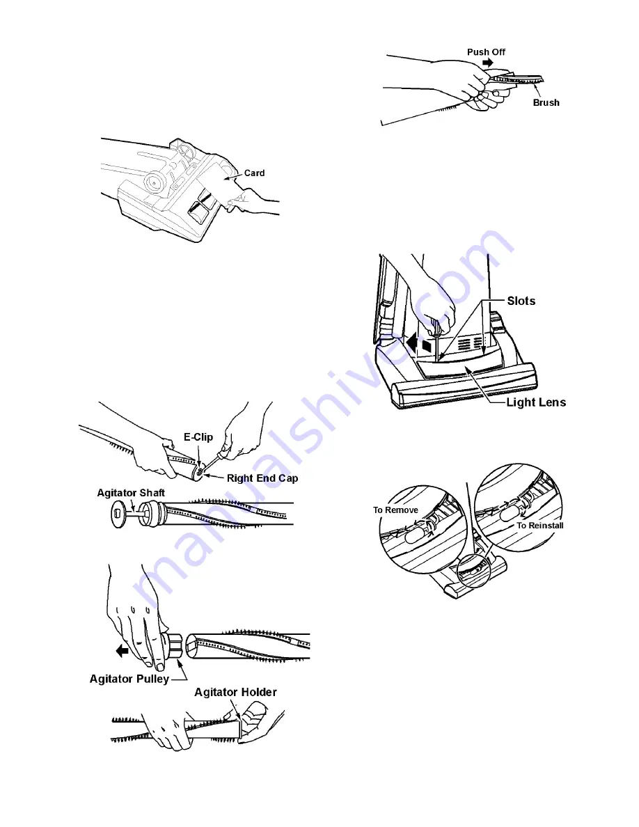
1. The agitator brushes should be replaced when the

brushes are worn. Brushes should be checked by holding
a card across the lower plate. If the bristles on the agitator
assembly do not touch the card you should replace all the
brushes for best cleaning results.

3.5.1.

Removal

1. Remove the lower plate as outlined in the LOWER

PLATE REPLACEMENT section.

2. Remove the agitator assembly as outlined in the agitator

assembly section.

3. The agitator assembly may now be disassembled and the

brushes replaced.

4. Carefully remove the E-clip from the agitator shaft, do not

misplace. Remove the right brush support. Pull the agita-
tor shaft out of the opposite end of the.

5. Pull or pry out the agitator pulley and agitator holder.

6. Push each brush out of the agitator.

7. Install new brushes by reversing procedure.
8. Reinstall agitator holder and agitator pulley completely.
9. Reinstall the agitator shaft, end cap and E-clip.

10. Position belt over agitator pulley on the agitator.

11. Reinstall agitator and lower plate.

3.6.

Headlight Bulb Replacement

1. Pry up light lens at slots.

2. Remove old bulb from the socket by pushing in while

turning counter-clockwise.

Summary of Contents for MC-V5269-00

Page 1: ... 00 Specifications are subject to change without notice for further improvement 2005 PANASONIC HOME APPLIANCES COMPANY DIVISION OF PANSONIC COR PORATION OF NORTH AMERICA All rights reserved Unauthorized copying and distribu tion is a violation of law ...

Page 2: ...2 1 WIRING DIAGRAM AND DRAWING 1 1 Wiring Diagram ...

Page 3: ...neral servicing it is necessary to eliminate pinching of any wire during reassembly After servicing any electrical compo nent or electrical enclosure the unit should be reassembled and checked for dielectric breakdown or current leakage ...

Page 4: ...4 2 EXPLODED VIEW AND PARTS LIST 2 1 Body 2 1 1 Exploded View ...

Page 5: ...TZB0Z Motor Case 1 26 AMC02L V00 Packing Rear Cover 1 27 AC19FARSZV06 Packing Motor Case 1 28 AXTN4 20BFY Screw Motor Case 4 Shipped 10 per package 29 AC92FBFTZ00 Fan Motor Unit 1 30 AC99GAMMZ00 Noise Suppressor 1 31 AMC02F E00 Motor Support Front 1 32 AC03FAFYZ00 Motor Support Rubber Rear 1 33 AMC37G V200U Wire Cord 1 34 AMC 1CTCE23 Wire Connector 2 35 AMC64B V2Z00 Handle 1 36 AC53EV0ZV07 Upper C...

Page 6: ...6 2 2 Nozzle Housing 2 2 1 Exploded View ...

Page 7: ...7A2VZV07 Pedal 1 15 AC58AAFVZ00 Spring Pedal 1 16 AMC51A 2V0 Shaft Pedal 1 17 AC11S2VZW00 Belt Cover Assembly 1 18 AC93HURZ00 Bulb Socket 1 19 AC28GADFZ00 Bulb 1 20 AC28SJPZ00 Belt 1 21 AC02ACRSZW0H Body Upper 1 22 AC12ACRSZW0H Cap Body 1 23 AMC68A V30 Screws 2 Shipped 10 per package 24 AC93QAGZZV06 Wheel 2 25 AC16CNXZ00 Shaft Wheel 2 26 AC91ACRSZ000 Lower Plate Assembly 1 Includes items 29 30 and...

Page 8: ... Agitator Assembly 1 Includes items 2 thru 11 2 AC85RBFT0000 Brush 6 Pcs 1 3 AC29SBVNZ000 Agitator Pulley 1 4 AC41SBVNZ000 Agitator Holder 1 5 AC44KBVNZ000 Filter 2 6 AC96DBVNZ000 End Cap Right 1 7 AC97DBVNZ000 End Cap Left 1 8 AC57RBVNZ000 Agitator Shaft 1 9 AC23FBVNZ000 Ring Clip 1 10 AC56RBYYZ000 Brush Holder 1 11 AC34SBYYZ000 Spacer Brushes 3 ...

Page 9: ...ing the two 2 latches out ward NOTE For general servicing it is necessary to eliminate pinching of any wire during reassembly After servicing any electrical component or electrical enclosure the unit should be reassembled and checked for dielectric break down or current leakage 3 2 Belt Replacement 3 2 1 Removal 1 Remove lower plate 2 Lift rear belt cover 3 Remove agitator by carefully lifting out...

Page 10: ...t position Insert a screwdriver under the back of the pedal cover and pry up to remove it from the pedal assembly Take care not to scratch the nozzle housing NOTE Every time the pedal cover is removed for any reason it should be replaced with a new one See Nozzle Exploded View and Parts List for correct replacement part number 2 Turn the vacuum over and remove the lower plate belt and agitator as ...

Page 11: ...tator assembly may now be disassembled and the brushes replaced 4 Carefully remove the E clip from the agitator shaft do not misplace Remove the right brush support Pull the agita tor shaft out of the opposite end of the 5 Pull or pry out the agitator pulley and agitator holder 6 Push each brush out of the agitator 7 Install new brushes by reversing procedure 8 Reinstall agitator holder and agitat...

Page 12: ... retainer and the dust compartment Attach wires with wire connec tors according to the wiring diagram in the front of this manual ONLY USE A NEW CORD RETAINER DO NOT REUSE A CORD RETAINER 2 For switch replacement only insert the new ON OFF switch with the numbers 1 2 3 facing toward you into the dust compartment until secured by the retaining tabs Use a wire tie in the location illustrated taking ...

Page 13: ...the lower plate agitator assembly belt the plas tic shaft and the nozzle housing as instructed in the respective removal sections 3 Turn the vacuum over to the front side 4 Remove the four 4 screws from the motor case and then remove the motor case 5 Disconnect the motor leads and remove the motor Remove the motor support rubber rear noise suppres sor and the motor support rubber front Place these...

Reviews: