background image

50

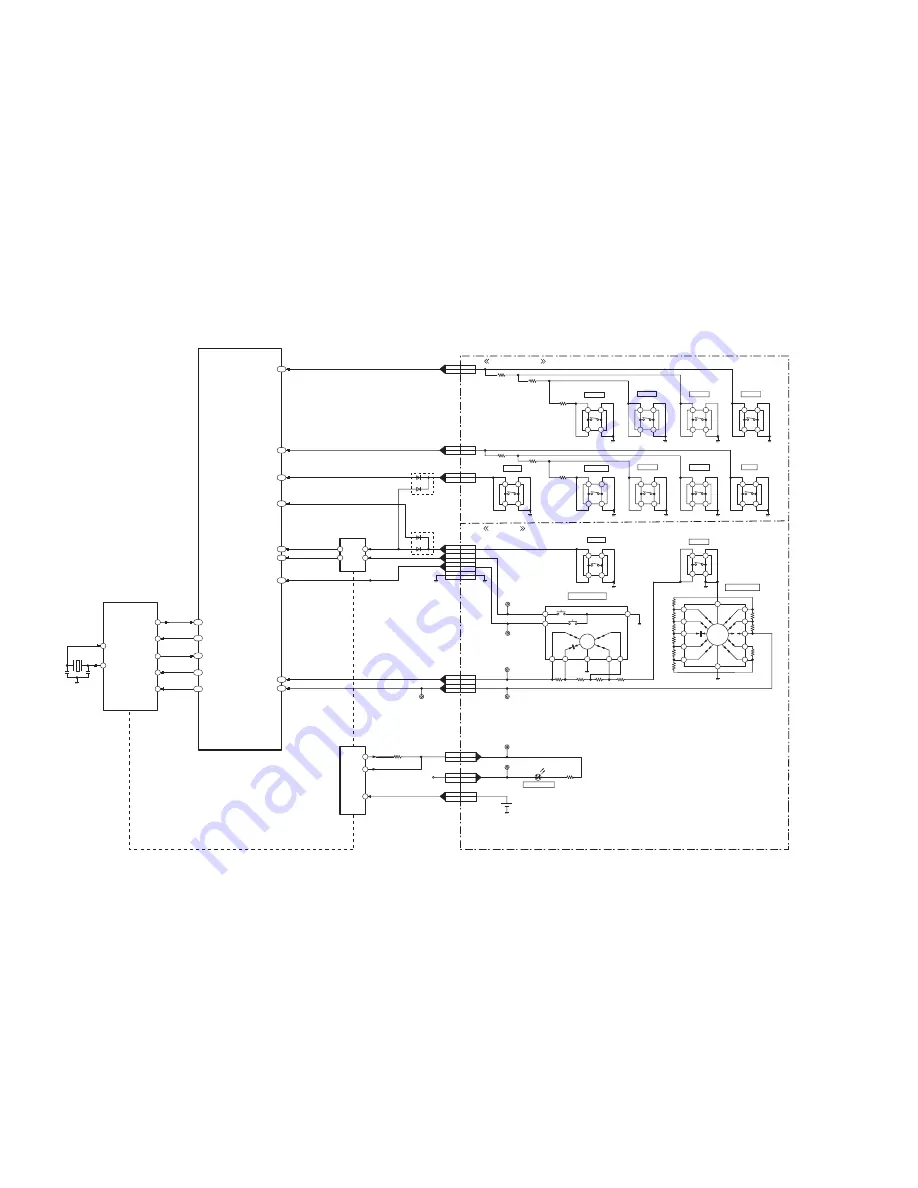
11.2. System Control Block Diagram

SHUT FULL

SYSCON CS

RSTB

POWER SW ON

DMC-TZ35/TZ36/ZS25 SYSTEM CONTROL BLOCK DIAGRAM

IC6001

(VENUS ENGINE)

SYSCON SI

67

IC9101

(SYSTEM IC)

SCCS

28

74

SO

71

SCSI

26

X9101

(32.768kHz)

SYSCON SO

SHUT HALF

87

54

IC9101

(SYSTEM IC)

OSC IN

OSC OUT

85

RESET OUT

70

SCSCLK

57

POWER SW ON H

POWER ON L

SHUTTER 0

SHUTTER HALF

IC9101

(SYSTEM IC)

SHUT HALF

C

WIDE
HI

WIDE
LO

TELE
LO

TELE
HI

83

SHUTTER 1

7

6

8

5

1

2

T W MOV

S9204

MOVIE

S9203

RIGHT

S9202

S9210

EXPOSURE

S9207

DISPLAY

S9208

DELETE

D9901

11

LEDOUT1

CROSS KEY IN

CL9907

CL9908

CL9903

CL9916

CL9917

S9904

MODE DIAL SW

S9901

ZOOM & SHUT SW

B9901
TIMER BACK UP
BATTERY

1

9

C

C

7

PW 3R6V

2

1

4

3

2

1

4

3

2

1

4

3

2

1

4

3

2

1

4

3

S9205

D9102

D9104

PLAY

2

1

4

3

S9902

POWER

2

1

4

3

2

1

4

3

2

1

4

3

S9206

MENU

2

1

4

3

S9903

LEFT

DOWN

8

6

5

4

3

CL9902

CL9002

REAR KEY IN

MODE DIAL

10

11

12

8

27

LEDOUT2

BATT

2

3

4

SYSCON SCK

AF ASSIST  LED

S9201

2

1

4

3

UP

AF LED K

BACKUP

PP9901

18

PS9004

PS9004

5

18

PS9004

11

PP9901

11

PP9901

5

PP9901

7

PP9901

9

PP9901

10

PP9901

24,25

PP9901

8

PS9004

24,25

7

9

10

8

PP9901

12

12

PS9004

PS9004

PS9004

PS9004

PS9004

M

C2

C1

S

A

SCN

iA

P

3D

SHUTTER 1

T W MOV

MODE DIAL

TOP P.C.B.

OPERATION P.C.B.

SYS RESET

PS9201

5

5

PP9006

PS9201

1

1

PP9006

PS9201

6

6

PP9006

AC20

AB18

AA23

AB23

PLAY

POWER ON L V

U21

U22

A16

W21

W22

N24

U23

C23

C20

E22

Summary of Contents for Lumix DMC-TZ35EB

Page 1: ...violation of law ORDER NO DSC1302001CE B26 Digital Camera Model No DMC TZ35EB DMC TZ35EE DMC TZ35EF DMC TZ35EG DMC TZ35EP DMC TZ35GA DMC TZ35GC DMC TZ35GN DMC TZ35SG DMC TZ36EG DMC ZS25P DMC ZS25PC DMC ZS25PU DMC ZS25GK Colours S Silver Type except DMC TZ35GN K Black Type ...

Page 2: ...e Memory Function 15 7 Service Fixture Tools 19 7 1 Service Fixture and Tools 19 7 2 When Replacing the Main P C B 19 7 3 Service Position 20 8 Disassembly and Assembly Instructions 21 8 1 Disassembly Flow Chart 21 8 2 P C B Location 21 8 3 Disassembly Procedure 22 8 4 Lens Disassembly Procedure 30 8 5 Assembly Procedure for Lens Revised Version 34 8 6 Removal of the MOS Unit 40 9 Measurements and...

Page 3: ...g exposed to shock hazards 1 2 Leakage Current Cold Check 1 Unplug the AC cord and connect a jumper between the two prongs on the plug 2 Measure the resistance value with an ohmmeter between the jumpered AC plug and each exposed metallic cabinet part on the equipment such as screwheads connectors control shafts etc When the exposed metallic part has a return path to the chassis the reading should ...

Page 4: ...Procedure 1 Refer to the disassemble procedure and remove the necessary parts unit 2 Install the insulation tube onto the lead part of Resistor ERG5SJ102 1kΩ 5W an equivalent type of resistor may be used 3 Place a resistor between both terminals of capacitor on the Flash P C B for approx 5 seconds 4 After discharging confirm that the capacitor voltage is lower than 10V using a voltmeter Fig F1 ...

Page 5: ...der ES devices 4 Use only an antistatic solder removal device Some solder removal devices not classified as can generate electrical charge sufficient to damage ES devices 5 Do not use freon propelled chemicals These can generate electrical charges sufficient to damage ES devices 6 Do not remove a replacement ES device from its protective package until immediately before you are ready to install it...

Page 6: ...ected to excessive heat or discharge It must therefore only be fitted in equipment designed specifically for its use Replacement batteries must be of the same type and manufacture They must be fitted in the same manner and location as the original battery with the correct polarity contacts observed Do not attempt to re charge the old battery or re use it for any other purpose It should be disposed...

Page 7: ...th 3 screws 2 of these 3 screws are locked after performing the Optical tilt adjustment During servicing if one of MOS fixing screws are loosened the Optical tilt adjustment must be performed About the Optical tilt adjustment refer to the 9 3 2 Adjustment Specifications for details NOTE It is necessary to use the DSC_Tilt software to allow the Optical tilt adjustment The Adjustment software DSC_Ti...

Page 8: ... of is printed on the P C B using the lead free solder To put lead free solder it should be well molten and mixed with the original lead free solder Remove the remaining lead free solder on the P C B cleanly for soldering of the new IC Since the melting point of the lead free solder is higher than that of the normal lead solder it takes the longer time to melt the lead free solder Use the solderin...

Page 9: ...B EF EG EP TZ36EG d DMC TZ35EE e DMC TZ35GN f DMC ZS25GK g DMC TZ35GA GC ZS25PU What is the difference is that the INITIAL SETTINGS data which is stored in Flash ROM mounted on Main P C B 3 4 1 Defining methods To define the model suffix to be serviced refer to the nameplate which is putted on the bottom side of the Unit Note After replacing the Main P C B be sure to achieve adjustment ...

Page 10: ...N 2 carefully Preparation 1 Attach the Battery to the unit 2 Set the mode dial to the PROGRAM AE mode Note If the mode dial position is other than PROGRAM AE mode it does not display the initial settings menu Step 1 The temporary cancellation of INITIAL SETTINGS While keep pressing UP of Cursor button and MOTION PICTURE button simultaneously turn the Power on Step 2 The cancellation of INITIAL SET...

Page 11: ...E 1 After replacing MAIN P C B There are four kinds of menu from as follows Except for DMC TZ35EG EF EB EP GA and TZ36EG models VEK0U02 is used as a Main P C B When Main P C B has just been replaced all of the model suffix are displayed as follows Four pages in total Only for DMC TZ35EG EF EB EP GA and TZ36EG models VEK0U03 is used as a Main P C B When Main P C B has just been replaced only 8 mode...

Page 12: ...uage when the unit is turned on again When the unit is connected to PC with USB cable it is detected as removable media 1 As for your reference major default setting condition is as shown in the following table Default setting After INITIAL SETTINGS MODEL VIDEO OUTPUT LANGUAGE DATE REMARKS a DMC TZ35 Japan domestic model NTSC Japanese Year Month Date b DMC TZ35EB PAL English Date Month Year c DMC ...

Page 13: ...13 4 Specifications The following specification is for DMC ZS25PC Some specifications may differ depending on model suffix ...

Page 14: ...14 5 Location of Controls and Components The following description is for DMC ZS25PC Some description may differ depending on model suffix ...

Page 15: ...f 2 How to display The error code can be displayed by ordering the following procedure Preparation 1 Attach the Battery to the unit 2 Set the mode dial to the PROGRAM AE mode Note Since this unit has built in memory it can be performed without inserting Memory Card Step 1 The temporary cancellation of INITIAL SETTINGS While keep pressing UP of Cursor button and MOTION PICTURE button simultaneously...

Page 16: ...ation IC7101 Gyro element or IC6001 VENUS ENGINE Zoom C B 0 10 Collapsible barrel Low detect error ZOOM L ZOOMm LENSu Collapsible barrel encoder always detects High Mechanical lock FP9005 11 signal line or IC6001 VENUS ENGINE 0 20 Collapsible barrel High detect error ZOOM H Collapsible barrel encoder always detects Low Mechanical lock FP9005 11 signal line or IC6001 VENUS ENGINE 0 30 Zoom motor se...

Page 17: ...nd IC9101 SYSTEM SOFT CPU Reset 30 0 0001 0007 NMI reset Non Mask able Interrupt 30000001 30000007 are caused by factors NMI RST MAIN P C B CPU ASIC hard Stop 38 0 0001 Camera task finish process time out LENS COM LENSu DSP Communication between Lens system and IC6001 VENUS ENGINE 0002 Camera task invalid code error DSP DSP IC6001 VENUS ENGINE 0100 File time out error in recording motion image IC6...

Page 18: ...ws 8 this error occurred under the condition of INITIAL SETTINGS has been released Example Factory assembling line before unit shipment Service mode etc It means that this error is occurred at service side 2 About indication 18 0 0 01 to 18 0 0 50 The third digit from the right shows one of the hexadecimal 0 to F character 4 How to exit from Error Code display mode Simply turn the power off Since ...

Page 19: ...re Tools 7 1 Service Fixture and Tools The following Service Fixture and tools are used for checking and servicing this unit 7 2 When Replacing the Main P C B After replacing the Main P C B be sure to achieve adjustment ...

Page 20: ...SCHARGE THE CAPACITOR ON Flash P C B The capacitor voltage is not lowered soon even if the AC Cord is unplugged or the battery is removed 2 Be careful of the high voltage circuit on Flash P C B 3 DO NOT allow other parts to touch the high voltage circuit on Flash P C B No Parts No Connection Form 1 VFK1895 PP9006 MAIN P C B PS9201 OPERATION P C B 40PIN B to B 2 RFKZ0545 PP9901 TOP P C B PS9904 Mai...

Page 21: ...21 8 Disassembly and Assembly Instructions 8 1 Disassembly Flow Chart 8 2 P C B Location ...

Page 22: ...et 5 LCD Unit Fig D5 1 Locking tab LCD Unit 6 Frame Plate Unit Fig D6 3 screws D 1 screw E 2 Locking tabs Frame Plate Unit 7 Lens Unit Fig D7 PCB Spacer 2 FPC Tapes FP9003 Flex FP9005 Flex Lens Unit 8 Main P C B Fig D8 1 Locking tab PP9901 Connector Main P C B Note When replacing DPR Sheet DPR Sheet 9 Top Case Unit Fig D9 4 Locking tabs Top Case Unit 10 Top P C B Fig D10 1 screw F 2 Locking tabs A...

Page 23: ...the protection sheet from the base sheet and fold the flap of the separator to the two sided tape side Fig D1 2 2 Slightly tilt the separator to prevent the two sided tape s adhesion Align the flap of the separator with the end of the rear case and then attach according to the fig below Fig D1 3 ...

Page 24: ... two sided tape 4 Remove the separator slowly and carefully Check if there is nothing sticking out from the rear case window frame Fig D1 4 8 3 2 Removal of the Front Case Unit Fig D2 8 3 3 Removal of the Side Ornament R Side Ornament L Unit Fig D3 ...

Page 25: ...25 8 3 4 Removal of the Operation P C B Fig D4 8 3 5 Removal of the LCD Unit Fig D5 ...

Page 26: ...26 8 3 6 Removal of the Frame Plate Unit Fig D6 8 3 7 Removal of the Lens Unit Fig D7 ...

Page 27: ...27 8 3 8 Removal of the Main P C B Fig D8 8 3 9 Removal of the Top Case Unit Fig D9 ...

Page 28: ...28 8 3 10 Removal of the Top P C B Fig D10 8 3 11 Removal of the Flash Unit Flash P C B Fig D11 ...

Page 29: ...29 8 3 12 Removal of the Battery Case Fig D12 ...

Page 30: ...t from the lens blow with dry air 4 Do not touch the lens surface 5 Use lens cleaning KIT BK VFK1900BK 6 Apply grease RFKZ0472 as shown on THE APPLICATION OF GREASE METHOD in the figure 7 Apply a light coat of grease using an object similar to a toothpick 8 4 1 Removal of the Master Flange Unit 1 Unscrew the 6 screws A 2 Remove the Shutter FPC 3 Remove the Lens FPC from the positioning boss 4 Remo...

Page 31: ...me 1st Lens Frame Unit 2nd Lens Frame Unit 3rd Lens Frame Unit Straight Frame and Both Side Cam Frame from the Fix Cam Frame Unit 8 4 3 Removal of the Decorative Frame Unit Outside Cam Frame 1st Lens Frame Unit 2nd Lens Frame Unit 3rd Lens Frame Unit Straight Frame and Both Side Cam Frame 1 Turn the Outside Cam Frame in the arrow 2 direction and then align the mark Drive Frame and Outside Cam Fram...

Page 32: ...f the 1st Lens Frame Unit 2nd Lens Frame Unit 3rd Lens Frame Unit Straight Frame and Both Side Cam Frame Hold the Both Side Cam Frame and turn it in the arrow direction Align the mark Outside Cam Frame and Both Side Cam Frame and then remove the Unit of 1st Lens Frame Unit 2nd Lens Frame Unit 3rd Lens Frame Unit Straight Frame and Both Side Cam Frame from the Outside Cam Frame 8 4 6 Removal of the...

Page 33: ...ction 8 4 8 Removal of the 3rd Lens Frame Unit Push the 3rd Lens Frame Unit in the arrow direction from the front of the Lens and remove the 3rd Lens Frame Unit from the Straight Frame and Both Side Cam Frame 8 4 9 Removal of the Straight Frame Turn the Straight Frame in the arrow direction and align the mark Straight Frame and Both Side Cam Frame in the direction as below Align the Bayonet Key wi...

Page 34: ...rough the concavity of Bayonet Key 3 Turn the Straight Frame about 90 degrees in the arrow direction so that the mark of Straight Frame comes close to the mark of Both Side Cam Frame As the drawing below indicates align the Grooves of Straight Frame with the one of Both Side Cam Frame 8 5 2 Insert the 3rd Lens Frame Unit and the 2nd Lens Frame Unit 1 Insert the 3rd Lens Frame Unit as the drawing b...

Page 35: ...en put the each Cam Pin of the 2nd Lens Frame Unit in the each Groove of the Straight Frame Unit 3 While pushing the 3rd Lens Frame Unit and the 2nd Lens Frame Unit turn the Straight Frame Unit in the arrow direction to the end about 30 degree Need to confirm that the two Lens Frames move smoothly when the Straight Frame Unit rotates in two directions ...

Page 36: ...ame Unit closer to the mark of the Outside Cam Frame Unit then turn the 1st Lens Frame Unit just a bit in the arrow direction about 2 degrees Hold the Cam Pin of the Both Side Frame Unit close to the Straight Key of the Straight Frame Unit 3 Insert the Straight Key and the Cam Pin into the following grooves 1 The Straight Key of the Straight Unit The groove for the Straight key of the Outside Cam ...

Page 37: ...rame Unit does not rotate when the Both Side Cam Frame Unit rotates It s the confirmation that previous insertion is done normally 8 5 4 Insert the Decorative Frame Unit 1 Hold the Straight Key Both Side Cam Frame turn it in the arrow direction and align with the Straight Key Outside Cam Frame 2 Insert 2 toothpicks rotation stopper in the position as below ...

Page 38: ...Unit 4 Turn the Decorative Frame Unite in the arrow 2 direction so that the mark Decorative Frame meets the mark Outside Cam Frame 8 5 5 Insert the Drive Frame Unit Align the mark Drive Frame and Outside Cam Frame and install the Unit of Decorative Frame Unit Outside Cam Frame 1st Lens Frame Unit 2nd Lens Frame Unite 3rd Lens Frame Unit Straight Frame and Both Side Cam Frame to the Drive Frame Uni...

Page 39: ...ote When Installing Refer to The Application of Grease Method when installing the Master Flange Unit Take Care not to damage the flex Take Care not to tuck in to the Master Flange Unit When inserting the Shutter Flex 1 Turn the Drive Frame Unit to the Wide position as below 2 Push the Hole of the Shutter Flex to the Boss of the Master Flange Unit tightly 3 Place the Shutter Flex following the Guid...

Page 40: ... the MOS Unit once the Torx screw A is loosened even a little the optical tilt adjustment is required When loosen the Torx screw A necessary the optical tilt adjustmentat the end of assembling Refer to item 9 3 2 To prevent the MOS Unit from catching the dust and dirt do not remove the MOS Unit except for replacing ...

Page 41: ... C B After replacing the Main P C B it is necessary to achieve adjustment 9 2 Before Disassembling the unit 9 2 1 Initial Setting Release The cameras specification are initially set in accordance with model suffix such as EB EG GK GC and so on Unless the initial setting is not released an automatic alignment software in the camera is not able to be executed when the alignment is carried out Note T...

Page 42: ...assembling the unit depending on each case ROM_BACKUP Method of Non PC backup 1 Insert the Memory Card into the camera 2 Set the camera to Temporary cancellation of the initial settings 3 Select the SETUP menu From the SETUP menu select ROM BACKUP Note This item is not listed on the customer s SET UP menu 4 When this ROM_BACKUP item is selected the following submenus are displayed 9 2 3 Light Box ...

Page 43: ... Status Adjustment Flag Setting Reset Not yet adjusted the status flag condition 1 After pressing the DISPLAY button the LCD monitor displays the Flag status screen Refer to Fig 3 2 2 Select item by pressing the cross keys Gray cursor is moved accordingly 3 Press the DELETE button Note The selected item s flag has been changed from F green to 0 yellow Refer to Fig 3 3 Flag conditions F green means...

Page 44: ...ng If one of these is moved accidentally start the adjustment again 3 Do not press any buttons keys until the default menu Fig 3 6 is displayed on the LCD monitor Otherwise adjustment data may not be stored properly 4 If the adjustment is interrupted accidentally the alignment data may not be properly saved in the Flash rom Fig 3 6 9 3 1 5 Finalizing the Adjustment 1 Several adjustment flags can b...

Page 45: ...x table shows the relation between the replaced part and the Necessary Adjustment When a part is replaced make sure to perform the necessary adjustment s in the order indicated The table below shows all the information necessary to perform each adjustment ...

Page 46: ...TTINGS first then release the INITIAL SETTINGS in order to proceed the electrical adjustment Note 1 If electrical adjustment or data re writing is executed before INITIAL SETTINGS suffix code list is never displayed and it cannot be chosen suitable suffix code 2 Never remove the battery during initial setting in process ...

Page 47: ...escribed in 3 4 2 INITIAL SETTINGS for details IMPORTANT 1 The initial setting should be done again after completing the alignment Otherwise the camera will not work properly Therefore as a warning the camera display a warning symbol on the LCD monitor every time the camera is turned off 2 Confirm that status of all adjustment flag show F Even if one of the adjustment flag shows 0 initial setting ...

Page 48: ...inder and LCD Panel with your hand When cleaning the lens use air Blower to blow off the dust When cleaning the LCD Panel dampen the lens cleaning paper with lens cleaner and the gently wipe the their surface Note The Lens Cleaning KIT VFK1900BK Only supplied as 10 set Box is available as Service Aid ...

Page 49: ...32 768kHz X6001 24MHz 27MHz IC1001 POWER SHUTTER IC9101 SYSTEM IC IC8001 FLASH CONTROL ZOOM 1 2 33 17 5 MEGA PIX SPEAKER IC7101 GYRO SENSOR DMC TZ35 TZ36 ZS25 OVERALL BLOCK DIAGRAM SPEAKER CONTROL 24mm 480mm OIS UNIT REAR OPERATION UNIT TOP OPERATION UNIT PRE CAMERA PROCESS J PEG COMP EXPAND MEDIA I F USB I F MAIN MICROPROCESSOR OIS CONTROL MOS DRIVE LENS DRIVE LCD DRIVE MICROPHONE AMP DIGITAL AV ...

Page 50: ...6 CL9917 S9904 MODE DIAL SW S9901 ZOOM SHUT SW B9901 TIMER BACK UP BATTERY 1 9 C C 7 PW 3R6V 2 1 4 3 2 1 4 3 2 1 4 3 2 1 4 3 2 1 4 3 S9205 D9102 D9104 PLAY 2 1 4 3 S9902 POWER 2 1 4 3 2 1 4 3 2 1 4 3 S9206 MENU 2 1 4 3 S9903 LEFT DOWN 8 6 5 4 3 CL9902 CL9002 REAR KEY IN MODE DIAL 10 11 12 8 27 LEDOUT2 BATT 2 3 4 SYSCON SCK AF ASSIST LED S9201 2 1 4 3 UP AF LED K BACKUP PP9901 18 PS9004 PS9004 5 18...

Page 51: ...A MCLK A DCLK A FCLK A DIN A DOUT SW USB VIDEO OUT CABLE DET USB CABLE IN SYSCON CS DAC TOP TOP TOP MAIN MAIN SDDET IN SDDET OUT FP9202 46 PS9201 16 PS9201 17 PS9201 19 PS9201 10 PS9201 18 PS9201 12 11 PS9201 20 PS9201 PS9201 9 PS9201 31 PS9201 26 PS9201 32 PS9201 8 PS9201 13 PS9201 14 PS9201 23 PS9201 15 PS9201 29 24 PS9201 30 PS9201 PS9201 22 PS9201 27 PS9201 28 PP9006 16 PP9006 17 PP9006 19 PP9...

Page 52: ...ID ZOOM MOTOR DC T W MOV CL8009 4 3 5 2 1 8 7 6 CL9903 CL9902 C SHUT HALF WIDE HI WIDE LO TELE LO TELE HI SHUT FULL CL9907 CL9908 IC7101 GYRO SENSOR 11 10 MOSI MISO 9 SCLK SHUTTER 0 SHUTTER 1 4 CD BARREL ENC FOCUS ENC ZOOM ENC FILTER LENS MOTOR DRIVE SYSTEM IC AMP B ch AMP A ch AMP C ch AMP D ch AMP X Y ch AMP X ch AMP Y ch LENS UNIT OIS UNIT VENUS ENGINE GYRO DI GYRO SCK GYRO DO PWM FA PWM FB PWM...

Page 53: ...EN1 3 2 VIN CL1003 CL1004 CL1421 CL1111 CL1212 CL1412 CL1005 DMC TZ35 TZ36 ZS25 POWER BLOCK DIAGRAM PP9901 24 25 PS9004 7 PP9901 7 PS9201 35 PP9006 35 PP9006 34 PS9201 34 PS9004 24 25 IC1410 REGULATOR 6 5 VOUT1 EN2 VOUT2 1 4 EN1 GND 3 2 VIN IC1220 REGULATOR 2 VSS 1 CE 3 VOUT 4 VIN IC1110 REGULATOR 2 3 VOUT CE VSS 1 4 VIN PP8001 PS9903 PP8001 1 5 PS9903 1 5 13 20 13 20 PP8001 PS9903 7 7 PP9901 PS99...

Page 54: ...PS9904 MIC_GND BATT MIC_IN BATT SP BATT BATT MIC_GND BATT BATT MOS UNIT LENS UNIT MAIN P C B FOIL SIDE COMPONENT SIDE OPERATION P C B FOIL SIDE COMPONENT SIDE LCD UNIT 10 30 15 12 13 11 14 26 27 25 29 28 32 8 33 6 2 1 3 4 5 7 9 31 36 38 39 40 37 34 35 20 17 18 16 19 21 22 24 23 GND D9 D5 USB_VBUS D13 D3 D1 SDATA D7 D11 D14 D0 GND GND PS9201 D15 GND VD D12 SCLK D10 LCD_RESET D8 CS D6 D4 HD D2 DCLK ...

Reviews: