

S-4
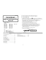
S4. Schematic Diagram
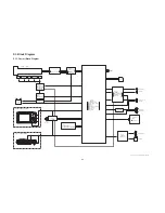
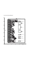
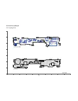
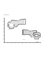
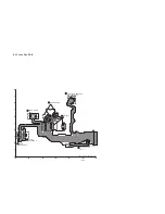
S4.1. Interconnection Diagram
DMC-FX37/FX38 INTERCONNECTION DIAGRAM
51
52
53
54
55
56
57
58
59
60
61
62
63
64
65
66
67
68
69
70
71
72
73
74
75
76
77
78
79
80
81
82
83
84
85
86
87
88
89
90
91
92
93
94
95
96
97
98
99
100
1
2
3
4
5
6
7
8
9
10
11
12
13
14
15
16
17
18
19
20
21
22
23
24
25
26
27
28
29
30
31
32
33
34
35
36
37
38
39
40
41
42
43
44
45
46
47
48
49
50
PS9801
PP9001
1
2
3
4
5
6
7
8
9
10
11
12
13
14
15
16
17
18
19
20
21
22
23
24
25
26
27
28
29
30
31
32
33
34
35
36
37
38
39
40
41
42
43
44
45
46
47
48
49
50
51
52
53
54
55
56
57
58
59
60
61
62
63
64
65
66
67
68
69
70
71
72
73
74
75
76
77
78
79
80
81
82
83
84
85
86
87
88
89
90
91
92
93
94
95
96
97
98
99
100
FP9801
FP9802
1
2
3
5
6
7
8
4
9
11
10
13
14
12
15
16
17
18
19
20
21
22
23
24
25
26
27
28
29
30
31
32
33
34
35
36
37
38
39
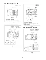
LCD UNIT
FP9002
NC
NC
BL MINUS
BL PLUS
4
3
2
1
: (COMPONENT SIDE)
PS8001
1
2
3
4
5
6
7
8
9
10
11
12
13
14
15
16
17
18
19
20
21
22
23
24
25
26
27
28
29
30
P8002
3
BA
TT
-
2
BA
TT+
1
BA
TT
THERMO
PP9802
BATTERY
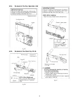
FLASH TOP P.C.B.
(COMPONENT SIDE)
SPEAKER
ET8001
ET8002
M8001
MICROPHONE
: (FOIL SIDE)
STB
CHG
LV
MIC
GND
MIC
IN
AG
N
D
MIC
REG
ANODE
SHUTTER
0
TELE
WIDE
BA
TT
THERMO
CA
THODE
FLASH
TRG
CCD
PO
WER
SE
SP
POS
SP
NEG
IGBT
VCC
BA
TT+
BA
TT+
BA
TT+
BA
TT+
STB
PWM
OUT
BA
TT
-
BA
TT
-
BA
TT
-
BA
TT
-
SHUTTER
1
UNREG
GND
UNREG
GND
P
O
W
E
RO
NL
MODE
DIAL
FRAME
GND
15
14
13
12
11
10
9
8
7
6
5
4
3
2
1
16
17
18
19
20
21
22
23
24
25
26
27
28
29
30
41
40
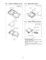
CCD
UNIT
LENS
UNIT
1
2
3
5
6
7
8
4
9
11
10
13
14
12
15
16
17
18
19
20
21
22
23
24
25
26
27
28
29
30
31
32
33
34
35
36
37
38
39
41
40
CON CHK
SUBSW1
V11L
V9L
V12
V10
V8
V7A
V6
V4
CCD GND
V3AV3B
V1A
CCD GND
G CCDOUT
CCD GND
SUBSW2
CCD GND
G HL
G H2
CON CHK
CCD THERMO
MSUBSW
V11R
V9R
V11
V9
V7S
V7B
V5AV5B
PW VL
PW VH
V2
V1B
CCD GND
CCD GND
MSUB
SUB
G R
G H1
CCD GND
42
43
45
44
ENC VCC
ABS
XVH-
XVH+
XDRV+
STAP
STBN
STAN
STBP
SH+
SH-
YDRV-
YVH+
YVH-
ZM2
ZM1
NC
1-ABS
2-LED CONT
NC
FBN
FAP
FAN
LED CONT
XVO+
XVO-
XDRV-
STAP
STBN
STAN
STBP
SH+
SH-
YDRV+
YVO-
YVO+
NC
ZM2
ZM1
1-LED CONT
ENC VCC
2-ABS
FBN
FAP
FBP
HD VIDEO Y
HD VIDEO PB
HD VIDEO PR
G SD VIDEO OUT
REC PLAY SW
A3R1V
D3V
D3V
BLT CTL
D GND
USB+
USB-
D GND
USB CAB IN
CCD POWER SE
CCD1
CCD3
CCD5
CCD7
CCD9
CCD11
SDWP
SDDATA0
SDDATA1
SDDATA2
SDDATA3
SDCMD
D GND
SDCLK
D GND
AFE CS
AFE SDATA
POWER SW ON
PWM FA
PWM FB
PWM IRISA
PWM IRISB
SHUTTER A
SHUTTER B
PWM XOIS
PWM YOIS
DAC LD
FZHP LED
ZENC LED
ZENC2
FZHP
D GND
GYRO DAY
GYRO DAX
MREF
MODE DIAL
TELE WIDE
BATT THERMO
STB CHG LV
D GND
CABLE DET
D1R8V
D1R8V
D1R2V
D1R2V
CCD THERMO
D GND
FCK
D GND
CCD0
CCD2
CCD4
CCD6
CCD8
CCD10
CCDHD
CCDVD
BL VDD
SHUT HALF
BL MINUS
SHUT FULL
STB PWM
SDCD SYS
D GND
27MCLK
D GND
AFE SCK
ACADP IN
MSUBSW
SYSCON CS
SYSCON SCLK
SYSCON SO
SYSCON SI
SYSCON RESET
POWER ON H
AUDIO PWM
DAC DI
DAC CK
SW UNREG
ZENC1
A GND
AUDIO AD IN
D GND
XPOS
YPOS
BA
TT+
BA
TT+
BA
TT+
BA
TT+
STB
PWM
OUT
BA
TT
-
BA
TT
-
BA
TT
-
BA
TT
-
SHUTTER
1
UNREG
GND
UNREG
GND
PO
WER
ON
L
MODE
DIAL
FRAME
GND
STB
CHG
LV
MIC
GND
MIC
IN
A
GND
MIC
REG
ANODE
SHUTTER
0
TELE
WIDE
BA
TT
THERMO
CA
THODE
FLASH
TRG
CCD
PO
WER
SE
SP
POS
SP
NEG
IGBT
VCC
MAIN P.C.B.
(FOIL SIDE)
SUB P.C.B.
(FOIL SIDE)
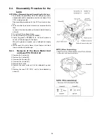
FP9003
GND
VDD
VCOML
SDI
CS
DB1
DB3
DB5
DB7
VSYNC
DCLK
VREG1OUT
C11M
C12M
VCC2
VCL
C13P
C23P
C22P
C21P
VGL
1
3
5
7
9
11
13
15
17
19
21
23
25
27
29
31
33
35
37
39
41
VCC1
VCOMH
IOVCC
SCL
DB0
DB2
DB4
DB6
HSYNC
GND
GND
DDVDH
C11P
C12P
VCIOUT
C13M
VGH
C23M
C22M
C21M
2
4
6
8
10
12
14
16
18
20
22
24
26
28
30
32
34
36
38
40
HD VIDEO Y
HD VIDEO PB
HD VIDEO PR
G SD VIDEO OUT
REC PLAY SW
A3R1V
D3V
D3V
BLT CTL
D GND
USB+
USB-
D GND
USB CAB IN
CCD POWER SE
CCD1
CCD3
CCD5
CCD7
CCD9
CCD11
SDWP
SDDATA0
SDDATA1
SDDATA2
SDDATA3
SDCMD
D GND
SDCLK
D GND
AFE CS
AFE SDATA
POWER SW ON
PWM FA
PWM FB
PWM IRISA
PWM IRISB
SHUTTER A
SHUTTER B
PWM XOIS
PWM YOIS
DAC LD
FZHP LED
ZENC LED
ZENC2
FZHP
D GND
GYRO DAY
GYRO DAX
MREF
MODE DIAL
TELE WIDE
BATT THERMO
STB CHG LV
D GND
CABLE DET
D1R8V
D1R8V
D1R2V
D1R2V
CCD THERMO
D GND
FCK
D GND
CCD0
CCD2
CCD4
CCD6
CCD8
CCD10
CCDHD
CCDVD
BL VDD
SHUT HALF
BL MINUS
SHUT FULL
STB PWM
SDCD SYS
D GND
27MCLK
D GND
AFE SCK
ACADP IN
MSUBSW
SYSCON CS
SYSCON SCLK
SYSCON SO
SYSCON SI
SYSCON RESET
POWER ON H
AUDIO PWM
DAC DI
DAC CK
SW UNREG
ZENC1
A GND
AUDIO AD IN
D GND
XPOS
YPOS