S-5
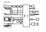
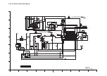
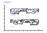
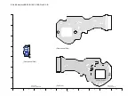
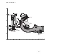
S4.2. Flash Top Schematic Diagram
%.
%.
%.
%.
%.
%.
%.
%.
%.
%.
%.
%.
%.
%
%
-)#
5
6.
6.
6.
'6
-$%&
-$%&
'6
6.
6.
'6
8/$
%
(-'
=?
%
(-,#
=?
%
%
(,,#
()%
%
%
()#
%
()#
R
%
3
$&(%)
4
-=?
4
4
4
4
4
M
/=?
4
4
-
4
/=&?
=?
4
/=&?
=?
4
M
4
-=&?
4
M
4
M
4
4
=?
--$##
25
%
(#(
8W(
-(#
5
5
-&$
5
-.%$
)&#
6
'4$5'47
(
'4$5'47
(
&'&4
8#
8#
=&'&4?
)(#
.
&
$'
,,%%
.$
%<$<
+%
$,$.2
3
.%$##
/
%
$#66
$#66
$#66
$#66
$#66
$#66
$#66
$#66
$#66
$#66
.#/2=?
.#/2=?
5
5
64)A)
64)(+456
5
5
5
&
)
)
64)5'%10&
5.''8'A)0&
1((
10
'
$#6A6*'4/1
$#6A6*'4/1
8
8
8
8
8
8
8
8
(
(
56$A%*)A.8
/+%A)0&
#A)0&
/+%A+0
/+%A4')
5*766'4A
5*766'4A
704')A)0&
704')A)0&
52A0')
52A215
6'.'A9+&'
(4#/'A)0&
/1&'A&+#.
24+06
704')
704')
56$A29/A176
5641$'A64)
QT
52.###
MGK
5#('6;A)0&
176
+0$ 8%%
+0#
)0&
219'4A10A.
%%&A219'4A%06
2.#;
+#761
#4'%
/#%41
5%0
/18+'
/'/1
+)$6A8%%
8CTKCVKQP%CVGIQT[
2
&/%(:
&/%(:
-<<
-<<
CAUTION: FOR CONTINUED PROTECTION AGAINST FIRE HAZARD,
REPLACE ONLY WITH THE SAME TYPE 1.25A 32V FUSE.
ATTENTION: POUR UNE PROTECTION CONTINUE LES RISQUES
D' INCENDIE N' UTILISERQUE DES FUSIBLE DE MÉME TYPE 1.25A 32V.
1.25A 32V
1.25A 32V
CAUTION: FOR CONTINUED PROTECTION AGAINST FIRE HAZARD,
REPLACE ONLY WITH THE SAME TYPE 1.5A 32V FUSE.
ATTENTION: POUR UNE PROTECTION CONTINUE LES RISQUES
D' INCENDIE N' UTILISERQUE DES FUSIBLE DE MÉME TYPE 1.5A 32V.
1.5A 32V
1.5A 32V
DMC-FX33
Flash Top
Schematic Diagram
10
9
8
7
6
5
4
3
2
1
G
F
E
D
C
B
A
Summary of Contents for Lumix DMC-FX33E
Page 12: ...12 4 Specifications ...
Page 13: ...13 5 Location of Controls and Components ...
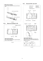
Page 19: ...19 8 Disassembly and Assembly Instructions 8 1 Disassembly Flow Chart 8 2 PCB Location ...
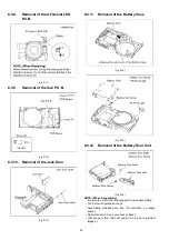
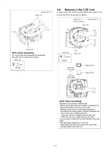
Page 21: ...21 Fig D2 8 3 2 Removal of the LCD Unit Fig D3 8 3 3 Removal of the Front Case Unit Fig D4 ...
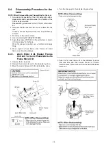
Page 23: ...23 Fig D8 8 3 6 Removal of the Main P C B Fig D9 8 3 7 Removal of the Lens Unit Fig D10 ...
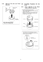
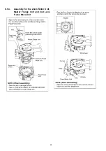
Page 28: ...28 8 5 4 Assembly for the Zoom Motor Unit Master Frange Unit and 2nd Lens Frame Move Unit ...

